12
420012001500 - 03182024 - Rev. 04
or
17e
17f
17h
17i
17j
17g
17k
Gas
17a
17b
17d
17c
ACCESSORIES BOX
BOITE ACCESSOIRES
For Qualified Technician
Installation Instructions
Pour technicien qualifié
instructions d’installation
Read the code
Lire le code
cod
e
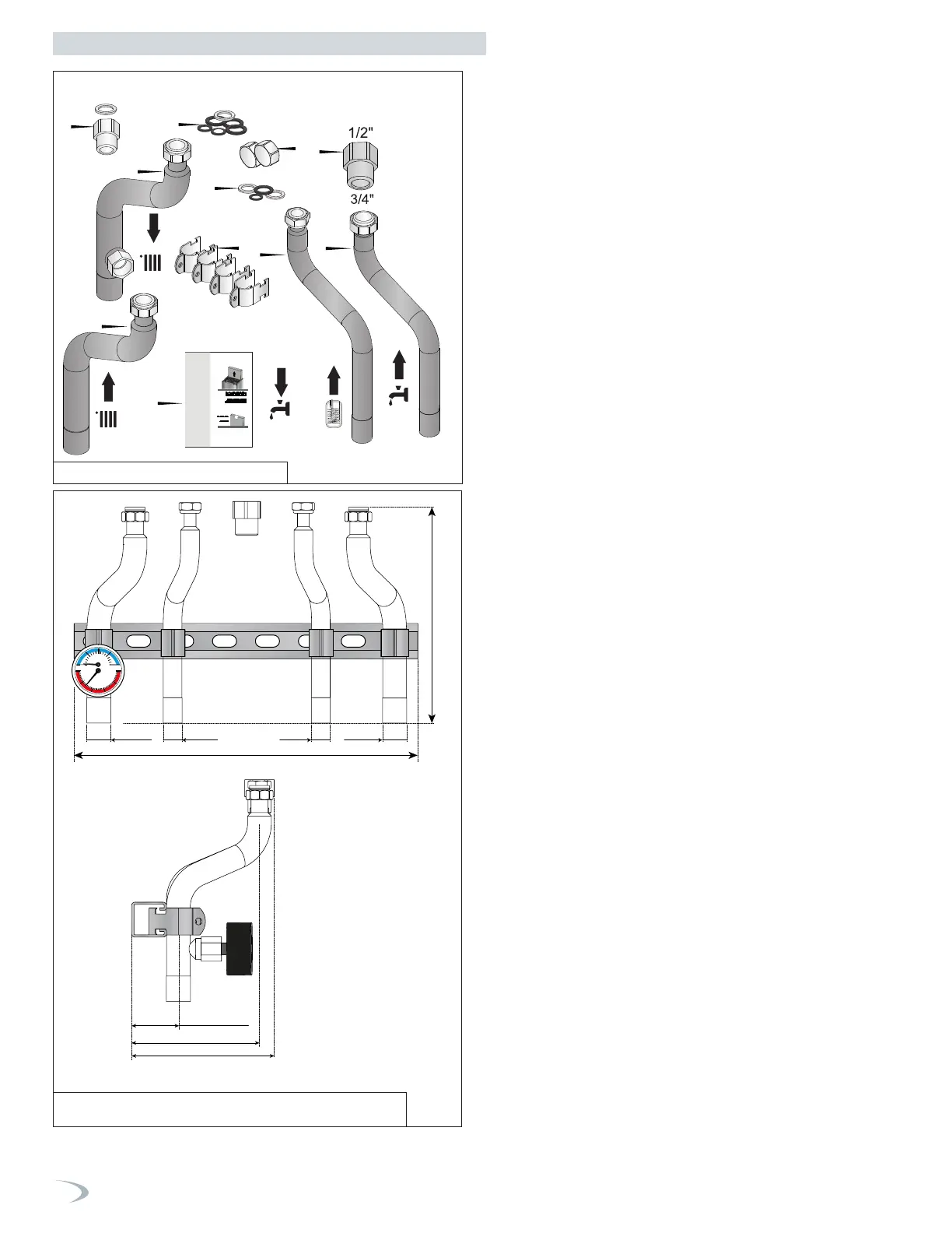
17 TRX150C / TRX120
Ø 1-1/8”
10" 1/16” (255 mm)
16” (406 mm)
Ø 1-1/8” Ø 7/8” Ø 7/8”
View from
the Front
6-11/16” (169 mm)
6-3/8” (162 mm)
2-3/16” (55 mm)
View from the Side
20
0
100 150
200
250
50
20
0
80
60
40
psi
Figure 2 - Included with the Boiler
Figure 3 - Adapter Kit Dimensions and Specifications -
Included with Adapter Kit
How the Boiler Operates
TRX condensing technology intelligently delivers hydronic heating
while maximizing efficiency. Outlined below are system features and
operation:
Stainless Steel Heat Exchanger
The highly efficient stainless steel heat exchanger is designed to
extract all available heat from the supply line before it is exhausted.
Modulating Combustion System
The combustion system modulates the output of the burner during
operation to match system demand and achieve the control set point
while in operation. The set point can change by internal or external
signals to enhance the overall performance of the system.
Control
The integrated control system monitors the system and regulates fan
speed to control boiler output. This allows the boiler to deliver only
the amount of heat energy required and nothing more.
The control can be set to monitor outdoor temperature through
an outdoor sensor or through internet weather (with optional WiFi
connection), use an optional room sensor, or use both outdoor
temperature and an optional room sensor to regulate boiler set point.
The system can be further enhanced by installing an indirect water
heater to provide domestic hot water.
The control can regulate the output of multiple boilers through its
cascade system function. The cascade system is capable of connecting
up to eight boilers together in such a way that they function as one
boiler system. This allows for greater turn down ratios and provides
systematic control of the multiple boilers in an installation to minimize
downtime and maximize efficiency.
The cascade system works by establishing one boiler as the master
and the other connected boilers as followers. The master boiler
requires a sensor to provide feedback on set point temperature
in order to adjust heating input from the connected boilers. Each
cascaded boiler will have its own pump to provide maximum flow and
control heat exchanger flow rate.
Text Display and Operational Display Icons
The display allows the user to change system parameters and monitor
system outputs.
Gas Valve
Senses suction from the blower, allowing gas to flow only if powered
and combustion air is flowing.
Integrated Venturi
Controls air and gas flow into the burner.
Burner
The high grade stainless steel burner uses premixed air and gas to
provide a wide range of firing rates.
Spark Ignition
The burner is ignited by applying high voltage through the system
spark electrode. The spark from the electrode ignites mixed gas off of
the burner.
Supply Water Temperature Sensor
This sensor monitors the boiler outlet water temperature (System
Supply). The control adjusts boiler firing rate so the supply
temperature will match the boiler set point.
Return Water Temperature Sensor
This sensor monitors boiler return water temperature (System Return).
Flue Sensor
Monitors flue temperature and adjusts firing rate.
Temperature and Pressure Gauge
Allows the user to monitor system temperature and pressure.
Electrical field connections with terminal strips
The electrical cover allows easy access to the clearly marked line
voltage and low voltage terminal strips to facilitate wiring the boiler.
Part 2 - Before You Start
 Loading...


