15
TRX Series II - Installation - Startup - Maintenance Instructions
CAUTION
CAUTION
WARNING
NOTE: A combustible door or removable panel is acceptable front
clearance.
All boilers eventually leak. Locate the boiler where any leakage from
the relief valve, related piping, tank, or connections will not result in
damage to surrounding areas or lower floors of the building. Any
boiler should be installed in such a manner that if it should leak the
resulting flow of water will not cause damage to the area in which it
is installed. If the boiler is installed in a location where a leak could
cause damage, it is required to provide containment measures. Such
measures include but are not limited to: a properly sized drain pan
installed beneath the boiler and piped to an open drain line, or
installing the boiler on a concrete floor pitched to a free flowing drain.
Failure to provide containment measures is the sole responsibility of
the owner and/or installer. Leakage damages ARE NOT covered by
warranty.
In addition, water leak detection devices and automatic water shutoff
valves are readily available at plumbing supply houses. IT IS HIGHLY
RECOMMENDED BY THE MANUFACTURER TO INSTALL WATER
LEAK DETECTION DEVICES AND AUTOMATIC SHUTOFF VALVES
IN ANY BOILER INSTALLATION WHERE A LEAKAGE OF WATER
COULD RESULT IN PROPERTY DAMAGES.
The boiler must be installed level for the condensate to properly flow
out of the collection system. Failure to do so will result in improper
appliance operation.
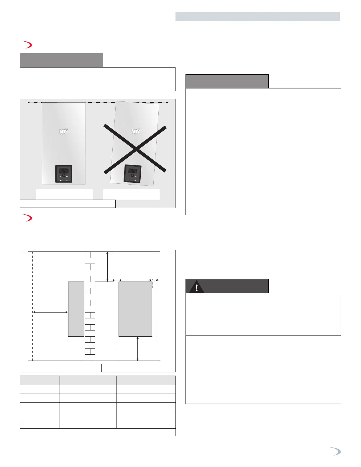
B. Leveling
C. Clearances for Service Access
NOTE: If you do not provide the minimum clearances shown in Figure
5 and Table 6 it might not be possible to service the boiler without
removing it from the space.
C
A
D
B B
Dimension Description Clearance
A Top 14” (355.6 mm)
B Right or Left Side 2” (50.8 mm)
C Front 18” (457.2 mm)
D Bottom 12” (304.8 mm)
Not Displayed Back 0” (0 mm)
NOTE: For closet installations, a combustible door or removable
panel is acceptable front clearance. A 3” minimum clearance must be
provided from the appliance front cover to the removable panel or
combustible door.
Minimum Clearances from Combustible Materials
• Hot water pipes - at least 1” from combustible materials
• Exhaust vent pipe - at least 1” from combustible materials
Correct installation
Incorrect installation
Figure 4 - Proper levelling
Figure 5 - Minimum Clearances
The space must be provided with correctly sized combustion/
ventilation air openings for all other appliances located in the
space with the boiler. For power venting installations using room air
for combustion, refer to the boiler venting section, this manual, for
descriptions of confined and unconfined spaces. Do not install the
boiler in an attic. The boiler cover must be securely fastened to prevent
the boiler from drawing air from the boiler room. This is particularly
important if the boiler is in a room with other appliances. Failure to
comply with the above warnings could result in substantial property
damage, severe personal injury, or death.
If the boiler area has a volume less than 150 ft3, it is considered a
Closet or Alcove. In the US/Canada, PVC vent pipe and fittings SHALL
NOT BE USED within the closet or alcove. Only approved CPVC,
Polypropylene, or Stainless Steel vent pipe and fittings may be used.
See Table 12 for a list of approved materials. Under all circumstances
proper ventilation must be provided.
Boiler Area Ventilation Air Openings - Closet Installations
If the boiler is installed in a closet or alcove the boiler area/room must
be ventilated.
EXCEPTION: If the boiler area/room has a volume of 150 ft
3
or greater,
ventilation of the boiler area/room is not required.
Each ventilation air opening must meet the minimum requirements of
1 in
2
per 1000 BTU/hr., but not less than 100 in
2
. The lower ventilation
opening must be located within 6 in. of the floor, while the upper
opening must be located 6 in. from the top of the space.
Part 3 - Prepare the Boiler for Installation
Table 6 - Minimum Installation and Service Clearances
 Loading...


