23
TRX Series II - Installation - Startup - Maintenance Instructions
26
2
7
9
12
13
6
8
11
10
3
4
5
14
15
18
19
20
21
24
22
17
16
23
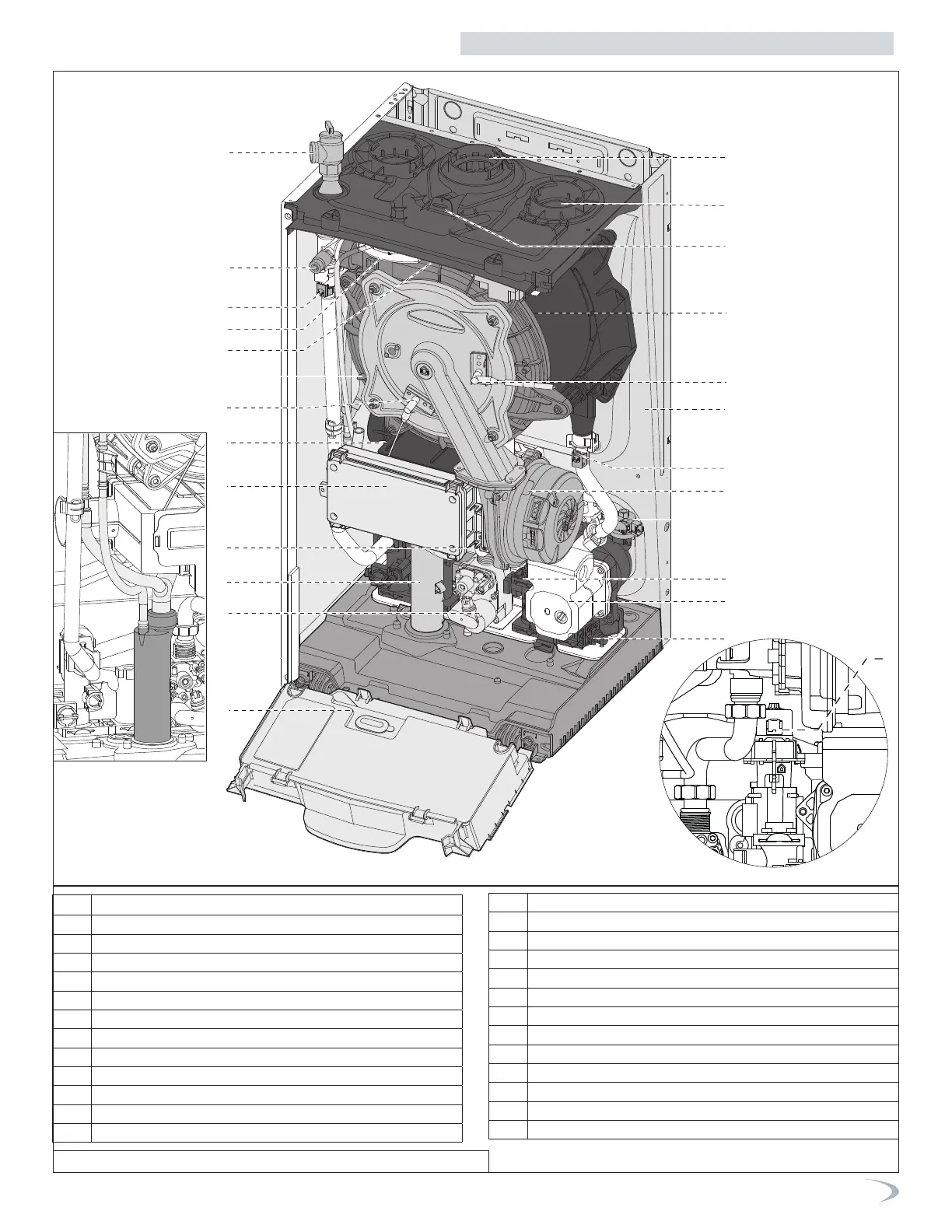
TRX110C - TRX150C
11
Figure 12 - Combi Boiler Component Locations and Descriptions
Part 3 - Prepare the Boiler for Installation
1.
Pressure relief valve
2.
Air purge valve
3.
Boiler outlet temperature sensor
4.
Air pressure switch
5.
Flue gas temperature sensor
6.
Main heat exchanger
7.
Flame detection electrode
8.
Silencer
9.
Junction box
10.
DHW heat exchanger
11 .
Condensate trap
12.
Gas valve
13.
Control panel
14 .
CH circuit filter
15.
Circulation Pump with auto air vent
16.
DHW Flow switch
17.
Water pressure switch
18.
Modulating Fan
19.
Boiler inlet temperature sensor
20.
Frame
21.
Ignition electrode
22.
Spark generator
23.
Combustion Analysis Test Point
24.
Air intake connection
25
Exhaust vent connection
26.
Diverter valve