28
420012001500 - 03182024 - Rev. 04
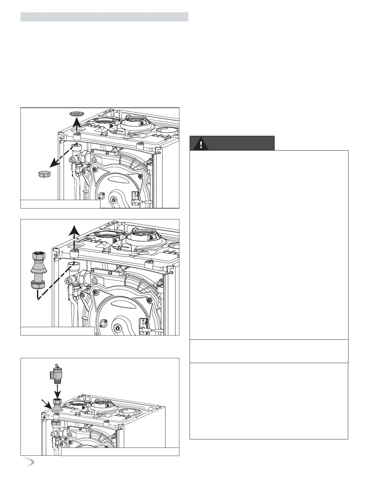
CH Loop
This boiler is provided with a CH pressure relief valve that complies
with the ANSI/ASME Boiler and Pressure Vessel Code, Section IV
(Heating Boilers). The included 30 psi CH Pressure Relief Valve must be
installed at the top of the boiler, using the included pipe adapter and
grommet, as illustrated below.
DO NOT install a relief valve with a pressure rating in excess of 50 psi
- the maximum allowable operating pressure of the boiler. The relief
valve capacity must exceed the BTU/H input capacity of the boiler. To
install the pressure relief valve proceed as follows:
1. Remove the plastic cover on the top of the boiler.
2. Remove the nut on the flow pipe.
3. Insert the pipe and gasket.
4. Connect the pressure relief valve and gasket.
NOTE: To maintain an airtight seal, ensure the gasket boot is
properly fitted into the top of the boiler cabinet.
DHW Loop (Combi Models)
The DHW piping must be provided with a DHW pressure relief valve
that complies with local codes, but not less than valves certified
as meeting the requirements of Relief Valves for Hot Water Supply
Systems, ANSI Z21.22 / CSA4.4 by a nationally recognized lab that
maintains periodic inspection of production listed equipment.
A DHW pressure relief valve is not included with the boiler, and is to be
field supplied and installed in the DHW piping. DO NOT install a DHW
relief valve with a pressure rating greater than 150 psi - the maximum
allowable operating pressure of the boiler’s DHW circuit.
After installing the relief valves and filling and pressurizing the system,
test the operation of the valves by lifting the levers.
Make sure the valves discharge freely. If a valve fails to operate
correctly, replace it with a new relief valve.
The relief valve capacity must exceed the BTU/H input capacity of the
boiler.
Figure 18 - Remove the Caps
Figure 19 - Insert the Pipe
Figure 20 - Connect CH Pressure Relief Valve
To avoid water damage or scalding due to relief valve operation:
Discharge line must be connected to relief valve outlet and run to a
safe place of disposal. Terminate the discharge line in a manner that
will prevent possibility of severe burns or property damage should the
relief valve discharge.
Discharge line must be as short as possible and the same size as the
valve discharge connection throughout its entire length.
Discharge line must pitch downward from the valve and terminate at
least 6” above the floor drain, making discharge clearly visible.
The discharge line shall terminate plain, not threaded, with a material
serviceable for temperatures of 375oF or greater.
Do not pipe discharge to any location where freezing could occur.
No valve may be installed between the relief valve and boiler or in the
discharge line. Do not plug or place any obstruction in the discharge
line.
Test the operation of the relief valve after filling and pressurizing the
system by lifting the lever. Make sure the valve discharges freely. If
the valve fails to operate correctly, immediately replace with a new
properly rated relief valve.
Test relief valve at least once annually to ensure the waterway is clear.
If valve does not operate, turn the boiler “off” and call a plumber
immediately.
Take care whenever operating relief valve to avoid scalding injury or
property damage.
FAILURE TO COMPLY WITH THE ABOVE GUIDELINES COULD
RESULT IN FAILURE OF RELIEF VALVE OPERATION, RESULTING
IN POSSIBILITY OF SUBSTANTIAL PROPERTY DAMAGE, SEVERE
PERSONAL INJURY, OR DEATH.
Do not thread a cap or plug into the relief valve or relief valve line
under any circumstances! Explosion and property damage, serious
injury, or death may result.
RE-INSPECTION OF RELIEF VALVES: Relief valves should
be inspected AT LEAST ONCE EVERY THREE YEARS, and
replaced if necessary, by a licensed plumbing contractor or
qualified service technician to ensure that the product has not been
affected by corrosive water conditions and to ensure that the valve
and discharge line have not been altered or tampered with illegally.
Certain naturally occuring conditions may corrode the valve and
its components over time, rendering the valve inoperative. Such
conditions can only be detected if the valve and its components are
physically removed and inspected. Do not attempt to conduct an
inspection on your own. Contact your plumbing contractor for a
re-inspection to assure continued safety.
Part 4 - Water Piping
WARNING
 Loading...


