47
TRX Series II - Installation - Startup - Maintenance Instructions
Part 5 - Venting
NOTE: These drawings are meant to demonstrate system venting only.
The installer is responsible for all equipment and detailing required by local codes.
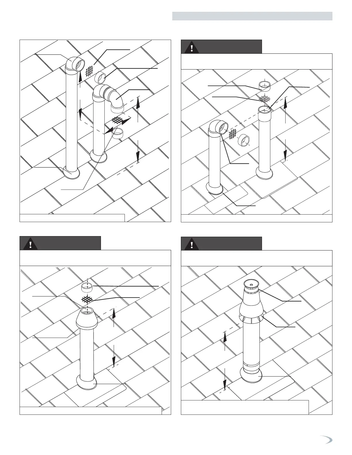
Roof Venting Options - Direct Vent Installation
Two Pipe Termination
Concentric Termination
Min. 12”
above grade
or snow level
Vent screen
Vent pipe piece to
retain vent screen
Exhaust
Option 2
Flashing
Exhaust
Option 2
Unbalanced Venting - Roof Exhaust Termination
Min. 12”
above grade
or snow level
Exhaust
Air-inlet
Flashing
Min. 12”
above grade
or snow level
Vent screen
Vent pipe piece to
retain vent screen
Exhaust center
Air-inlet around
perimeter
Flashing
Figure illustrates two options for exhaust termination only. Neither vent
pipe illustrated is intended for combustion air intake.
Refer to documentation included with termination kit for complete
installation instructions.
Refer to documentation included with termination kit for complete
installation instructions.
Figure 52 - Roof Concentric Termination (with Optional IPEX kit)
Figure 51 - Unbalanced Venting - Roof Exhaust Termination Options
WARNING
WARNING
WARNING
Figure 53 - Roof Concentric Termination
(with Optional Duravent / InnoFlue Kit)
Exhaust
Vent screen
Flashing
4 in. min
Vertical
Min. 18”
Min. 12”
above grade
or snow level
Air-inlet
Vent pipe piece to
retain vent screen
Figure 50 - Two Pipe Roof Venting Detail
 Loading...