94
Part 14 - Maintenance
Failure to replace the sealing rings will result in gas leaks, and
could cause an explosion or re, substantial property damage,
severe personal injury, or death.
DANGER
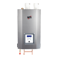
Replace the Main PCB
1. Fold down the electronics box.
2. Unlock the two clips and open the electronics box cover.
3. Disconnect the electrical connections.
4. Unhook the controller board and remove it.
5. Proceed in reverse order to install the new PCB.
6. Follow the instructions provided with the replacement PCB kit for
setting all necessary parameters.
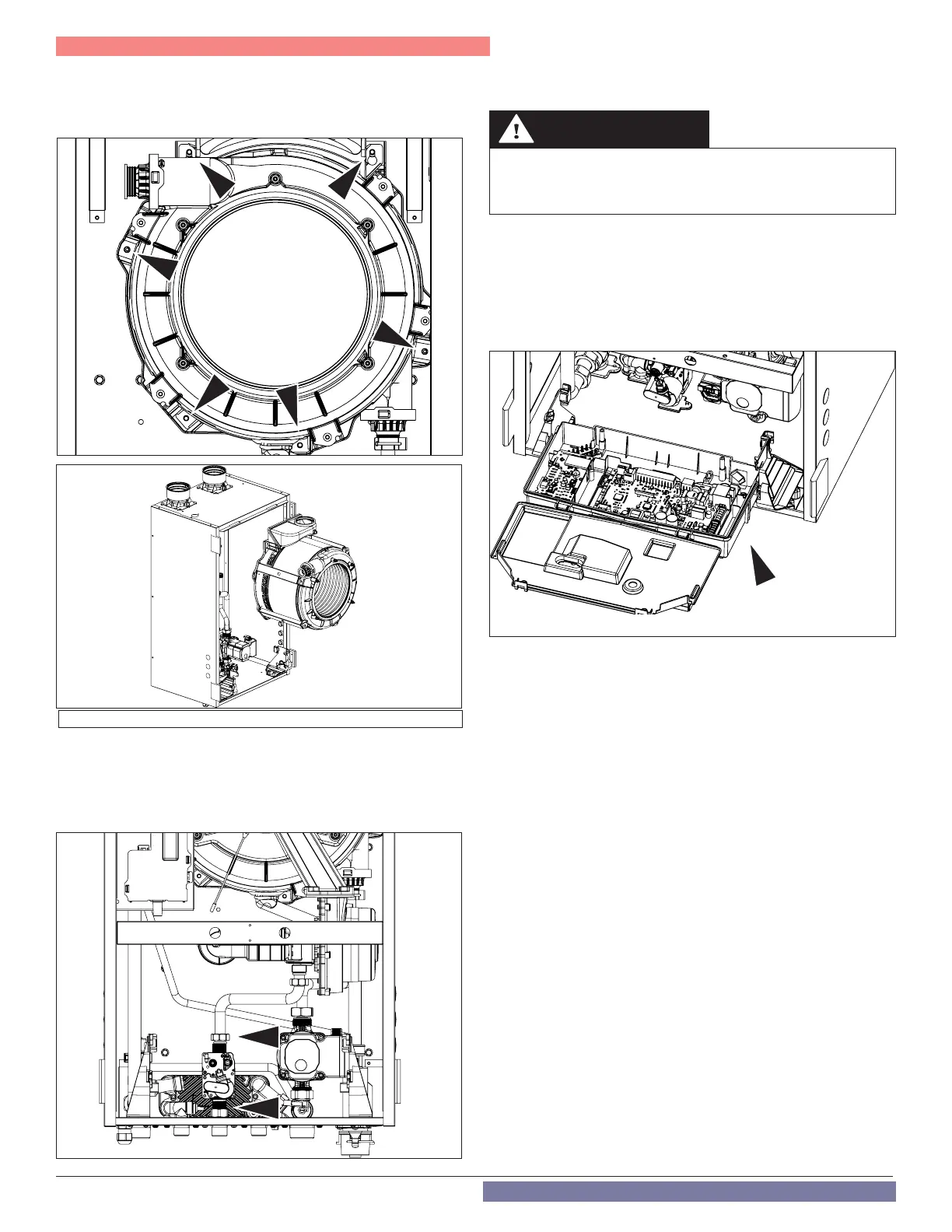
Figure 92 - Remove the Heat Exchanger
Figure 93 - Disconnect the Gas Line
Replacing the Gas Valve
1. First remove the gas pipe as described in Cleaning the Heat
Exchanger Combustion Chamber.
2. Remove the electrical connection from the gas valve.
3. Remove the two nuts above and below the gas valve. See Figure
93.
Figure 94 - Disconnect the Main PCB
4. Remove the gas valve.
5. Reinstall the new gas valve in reverse order.
6. BE SURE TO USE NEW SEALING RINGS.
E. After Maintenance is Complete
Functional Test
After maintenance is complete, ensure the CH circuit is lled and
purged with a pressure of 12 psi. Ensure the DHW circuit is lled and
purged.
1. Power the boiler on.
2. If necessary, purge air again from the CH and DHW circuits.
3. Check the boiler and system settings and components. Ensure all
adjustments are working properly.
4. Ensure the exhaust pipe is connected properly.
5. Reinstall the boiler front cover.
6. If necessary, set the maintenance interval.
Inform the User
1. Inform the user of any changes / adjustments / replacements in the
system.
2. Ensure the user understands how the system works.
3. Hand the instructions to the user. Ensure the instructions will be
kept close to the unit.
4. Have the user perform these regular tasks:
• Check the system water pressure regularly.
• If necessary, restore pressure and vent the system.
• Set the setpoints and control systems to ensure correct and
economical control of the system.
• Have the system serviced in accordance with regulations at
regular intervals.
• NEVER attempt to service the boiler or adjust the combustion
system.
8. Remove the six (6) xing screws from the heat exchanger. If
accessing the screws on the left part of the heat exchanger is
dicult remove the lateral panel.
9. Proceed in the reverse order to install the new heat exchanger.
7. Ensure there are no gas leaks.