5
27. 10. 20. Document Number 671590Nuaire | Western Industrial Estate | Caerphilly | CF83 1NA | nuaire.co.uk
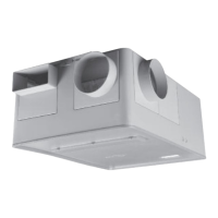
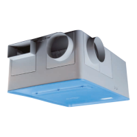
AVT-(R/X)
Installation Manual
4.4 Constant Pressure Units (AVTCP)
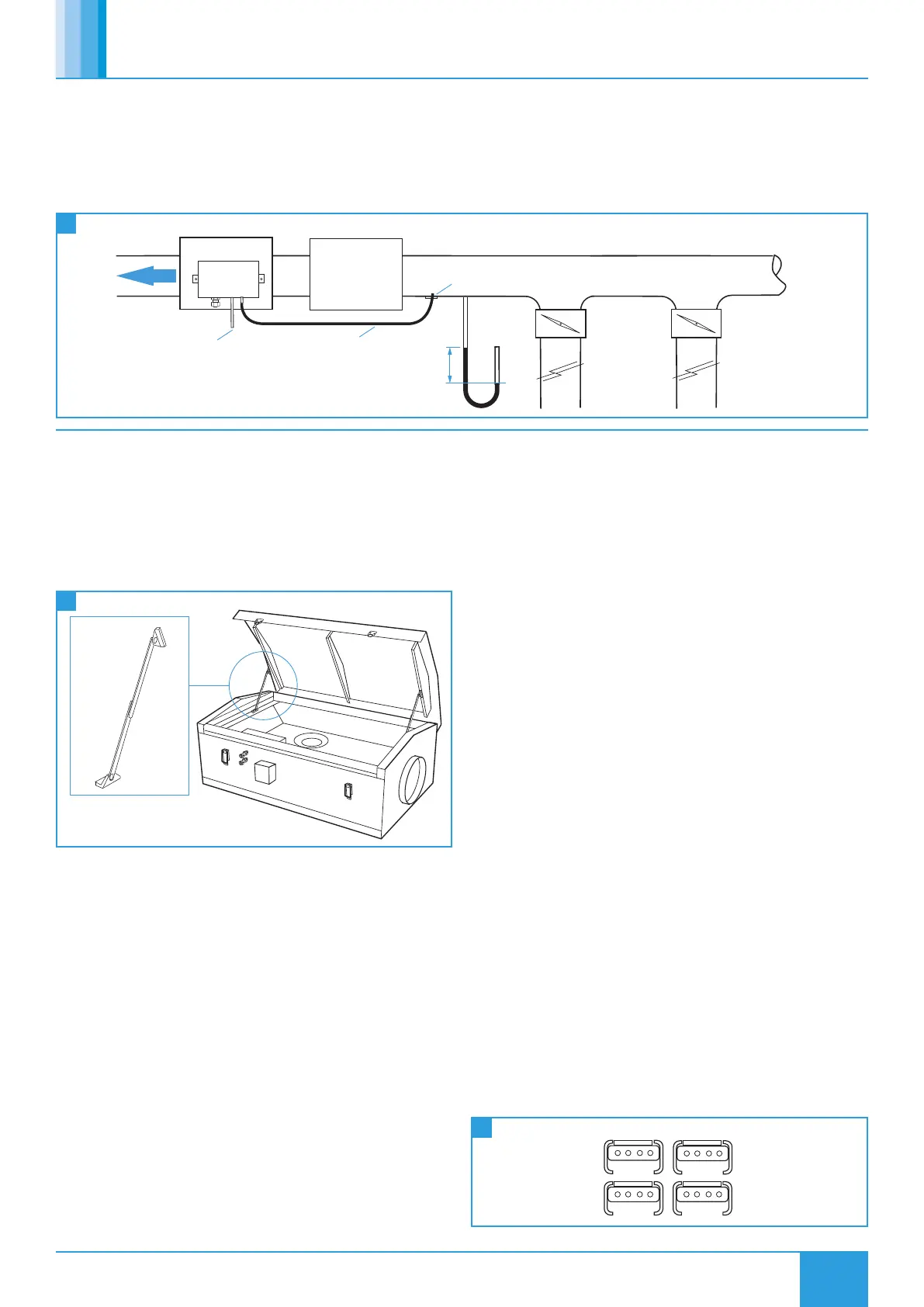
Ecosmart constant pressure extract fans are supplied to control the
static pressure at the fan inlet. This set up is suitable for the majority of
applications.
However, when ancillaries with high pressure losses are fitted to the
fan’s inlet side, the low pressure tapping needs to be moved from
the fan chamber to a location upstream of the ancillaries (Figure 11).
Failure to do this will result in excessive pressure being applied to
the dampers at the rooms when the system is running in trickle
mode.
11
Constant Pressure Arrangement
Riser
Ancillaries e.g.
Silencer, Filter,
Heat Recovery
Unit
Riser
Inlet
Pressure
Branch
Balancing
Damper
Branch
Balancing
Damper
Extract Fan
To atmosphere
High Low
Pressure
Sensor
Flexible tubing
New Pressure Tapping
Airflow
Airflow
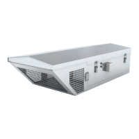
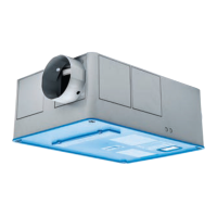
4.5 Unit Access
To gain access to blowers for annual maintenance, and connections to
control board, release tool operated latch and raise roof ensuring that
the two stays are locked into place.
Make sure work is carried out only when weather conditions do not
put the health and safety of workers and public in danger.
Reference: Health & Safety in Roof Work HSG33.
12
AVT-R/X Access
5.0 ELECTRICAL INSTALLATION
Before commencing work make sure that the unit, switched live
and Nuaire control are electrically isolated from the mains supply.
Because the run and start currents depend upon the duty and
associated ductwork of an individual unit, run currents will be
exceeded if the unit is operated with its cover removed. It is therefore
recommended that the unit is not run for prolonged periods in this
condition.
5.1 Post Installation Testing
•Ensure that the fan unit and any specified controls are fitted
securely according to the instructions.
•Switch on the mains supply.
•Push the test button to run the unit fan and check it runs
satisfactorily.
•If a switched live signal is used, activate this signal and check that
the fan runs. De-activate the switched live signal and check the
run-on time; adjust if necessary.
•Adjust the set point of any sensors and PIR; check they function
correctly.
•Adjust the maximum and minimum airflow (if required) by
following the commissioning procedures.
5.2 Wiring Connections
5.2.1 Mains Connections
Mains cables should be suitably sized and terminated at terminals
shown on the appropriate diagram.
5.2.2 Control Connections
NET - 4 IDC plug-in connectors are provided for the connection of
compatible sensors, manual controls and for linking the fans together
under a common control. If more than 4 connections are required,
the junction box (product code ES-JB) should be used (see data cable
installation).
13
Control Connections
 Loading...