6
27. 10. 20. Document Number 671590Nuaire | Western Industrial Estate | Caerphilly | CF83 1NA | nuaire.co.uk
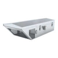
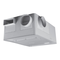
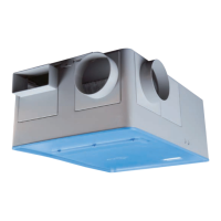
AVT-(R/X)
Installation Manual
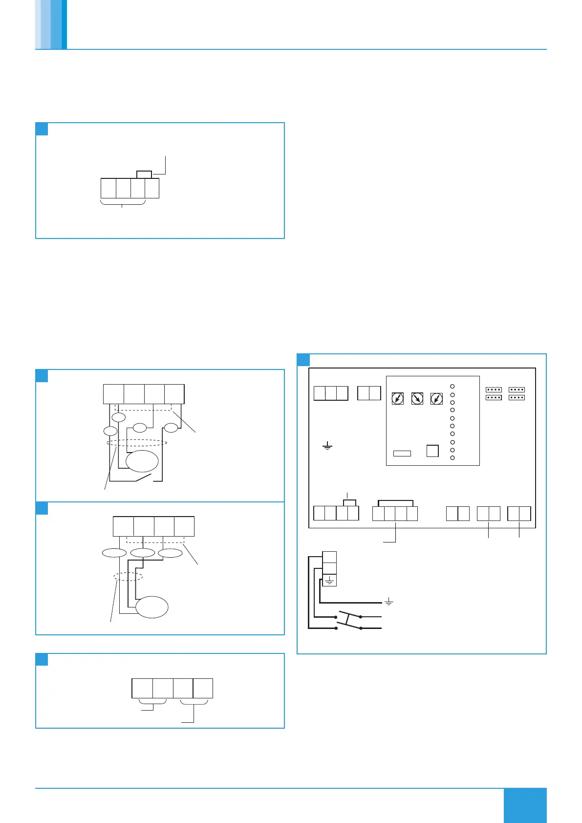
5.2.3 Switched Live (SL) Terminal
A signal of 100-230V a.c. will activate the fan from either its off
state or trickle state (see setting to work-trickle switch). When the
SL is disconnected the fan will over-run (see setting to work-timer
adjustment). Do not take this signal from an isolating transformer.
14
Switched Live Terminal
Mains Connection
Pre-wired
230V 50Hz 1Phase
Remove link if Switched Live signal,
an enabler or BMS signal is connected
Terminals or PCB
N E L SL
5.2.4 Damper Connections
OP - 230V 50Hz 1A max supply to open the damper
CL - 230V 50Hz 1A max supply to close the damper
N - Neutral supply to damper
RET - 230V ac return signal from the damper limit switch indicates the
damper has reached its operating position. If the return signal is not
present, the fan will wait for 1 minute before starting. If a damper is
not fitted, connect a link wire from OP to RET. This will cancel the
delay.
15
Drive Open / Drive Close Damper Connection
All wiring is 1PH 230V 50Hz
of 1 minute is
imposed to the
enable the damper
to open.
To override the
delay fit a link here.
230V
motor
OP CL N RET
2
S4
S6
1
16
Drive Open / Spring Close Damper Connection
All wiring is 1PH 230V 50Hz
A fan starting delay
of 1 minute is
imposed to the
enable the damper
to open.
To override the
delay fit a link here.
A fan starting delay
of 1 minute is
imposed to the
enable the damper
to open.
To override the
delay fit a link here.
OP
White Brown Blue
CL N RET
230V
motor
5.2.5 Volt Free Relay Contacts
17
Volt Free Relay Contacts
RUN FAULT
Run Signal
Fault Signal
5.2.6 Data Cable Installation
A 4-core SELV data cable is used to connect devices such as sensors to
the fan and for interconnecting multiple fan units.
For good EMC engineering practice, any sensor or low voltage data
cables should not be placed within 50mm of mains cables or placed
on the same cable tray or conduit as mains cables.
The maximum cable run between any two devices is 300m when it
is installed in accordance with the instructions. The total data cable
length used in any system must be less than 1000m. Keep the number
of cable joints to a minimum to ensure the best data transmission
efficiency between devices + 50m or less for ES-LCD.
5.2.7 Maximum Number Of Devices
The maximum number of devices (including fans) that can be
connected together via the data cable is 32, irrespective of their
functions.
5.3 Wiring Diagrams
All inter-connections between circuit boards, blowers and sensors
are made at the factory. These diagrams only show the essential
field wiring points for clarity.
*Remove link wire if switched live signal, an enabler or BMS signal is
connected.
5.3.1 AVT 1-8
230V - 50Hz Supply
Local isolator (by others)
L
N
N
L
Damper Connections
Run
Signal
Fault
Signal
NET
connections
for Ecosmart
devices
Min Max SL run
on
Trickle
0 1
Test
Link wire see note*
ES-CO2
Connection
BMS
Input
Signal
0-10V
0V
Ecosmart
Pwr
Standby
Fan 1
Heating
Fan 2
Cooling
Fault
TX
RX
Frost
N
L
SL
DP
CL
N
RET
Heat
Demand
Fault Run
E
18 AVT 1-8 Wiring
 Loading...