7
27. 10. 20. Document Number 671590Nuaire | Western Industrial Estate | Caerphilly | CF83 1NA | nuaire.co.uk
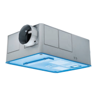
AVT-(R/X)
Installation Manual
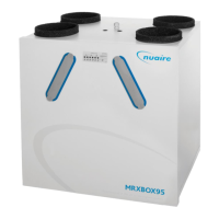
5.3.2 AVT 9
Damper Connections
Run
Signal
Fault
Signal
NET
connections
for Ecosmart
devices
Trickle
10
Link wire see note*
Test
ES-CO2
Connection
BMS
Input
Signal
0V
0-10V
Ecosmart
Pwr
Standby
Fan 1
Fan 2
Heating
Cooling
Fault
TX
RX
Frost
N
L
SL
DP
CL
N
RET
Heat
Demand
FaultRun
N L1 L2 L3
L3
L2
L1
N
400V - 3ph 50Hz Supply
Local isolator (by others)
E
Min Max SL run
on
19 AVT 9 Wiring
5.3.3 Control Module
Volt Free
Contact
RUN signal
0.5A inductive
5A resistive
Volt Free
Contact
Connections
FAULT signal
to Damper
N
L
SL
RUN FAULT
DP
CL
N
RET
400V 3ph 50Hz supply
Switch live signal
(if required)
connections
No user
NET connections for
ECOSMART devices
connections
CO
2
sensor
0
+ve signal
from BMS
Remove this link wire if
a switched live signal is
connected to terminal SL
NOTE: Also remove link if a
BMS is connected.
Also remove link if an enabling
device is connected in the 'NET'
ECOSMART NET
L3L2 L1 N
Ribbon cable
to commissioning
box
N L1 L2 L3
20
Control Module Wiring Diagram
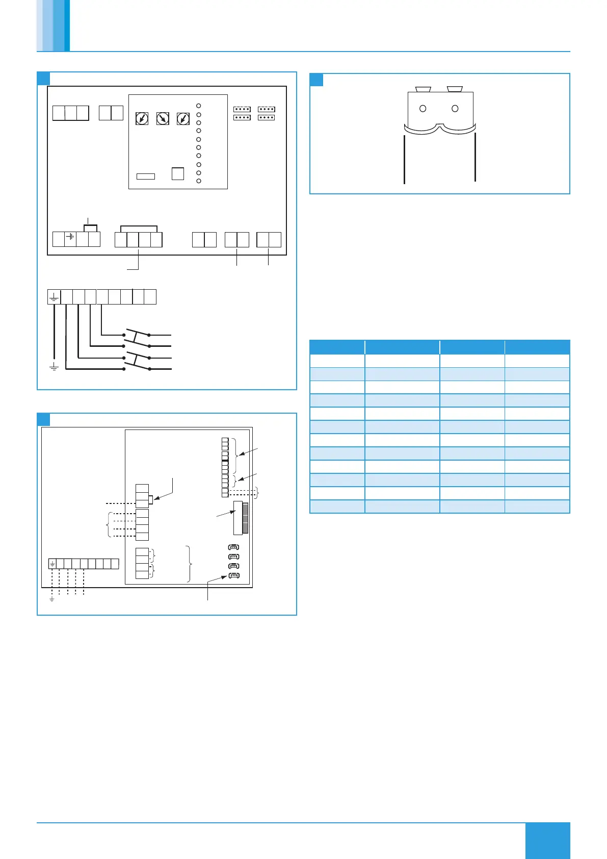
5.4 BMS Input Signals
21
BMS Connector
BMS Input Signals and other low voltage cables should Follow the basic
principles set out in (Section 5.2.6).
The BMS connection is made with a plug-in connector via the socket
(Figure 21). To ensure the connection is made only by suitably qualified
and authorised personnel, the plug is not supplied. It is available from
R S Components, Part No. 403-875 or Farnell, Part No. 963-021.
Reversal of the BMS connection will damage the control.
The system’s response to a 0-10V dc BMS signal is given in the table
below. The voltage tolerance is +/- 125mV and is measured at the fans
terminal. The BMS signal will override any sensors and user control
connected in the system.
Ventilation Mode Cooling Mode* Heating Mode*
Local Control 0.00 - -
OFF/ Trickle 0.25 - -
Speed 1 0.50 0.75 1.00
Speed 2 1.50 1.75 2.00
Speed 3 2.50 2.75 3.00
Speed 4 3.50 3.75 4.00
Speed 5 4.50 4.75 5.00
Speed 6 5.50 5.75 6.00
Speed 7 6.50 6.75 7.00
Speed 8 7.50 7.75 8.00
Speed 9 8.50 8.75 9.00
Speed 10 9.50 9.75 10.00
* Only available on relevant unit.
 Loading...