5 - 12 en-938821/2
5.2.1.2 Part Origin Shift Introduction
By bringing the spindle into contact with the part, this procedure enables the CNC to measure the part origin shifts
(DAT1) directly.
When a setting piece is inserted between the spindle and the part, this method can still be used, but the part origin
shift values must be modified via the keyboard to take into account the dimensions of the setting piece.
The procedure described below is only one of the possible methods of entering the part origin shift values.
Requirements
Homing procedure performed (See 5.1.2).
No mode being executed.
Actions
For each axis:
Manually bring the spindle datum into contact with the origin surface of the
reference part.
Select the origin setting mode (See 5.2.1.1).
Enter "*[axis name]". ☞
Transfer of the spindle datum measurement dimension of the corresponding axis to DAT1 which is then displayed on
screen.
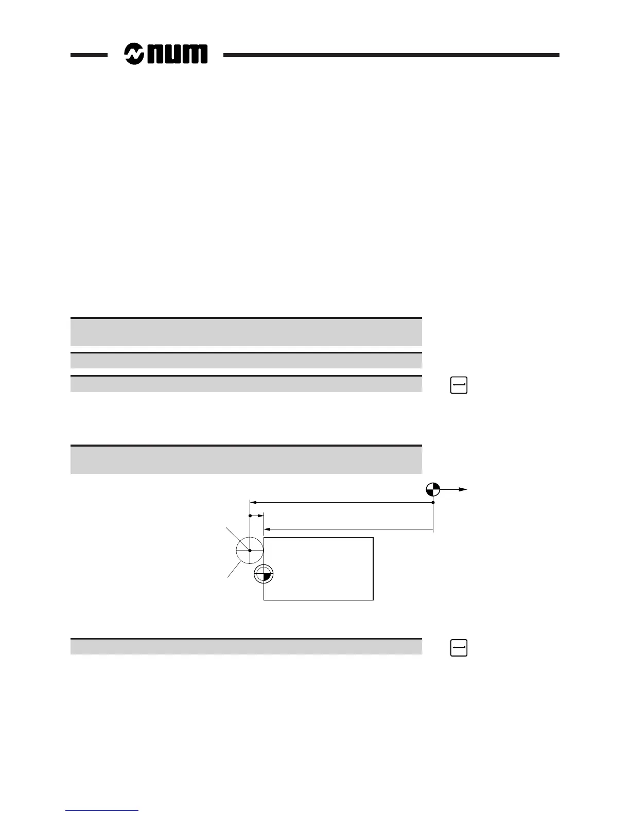
If using a test bar for example:
Calculate the real value of DAT1 taking into account the dimensions of the
test bar (See diagram).
Op
Real DAT1
Op/spindle datum shift
OM
Test bar Ø 100
Displayed DAT1
Spindle
datum
real DAT1 = displayed DAT1 + Op/spindle datum shift (algebraic value)
Enter "[axis name][real DAT1]". ☞
The real DAT1 is displayed.