1
13
25 contacts
25
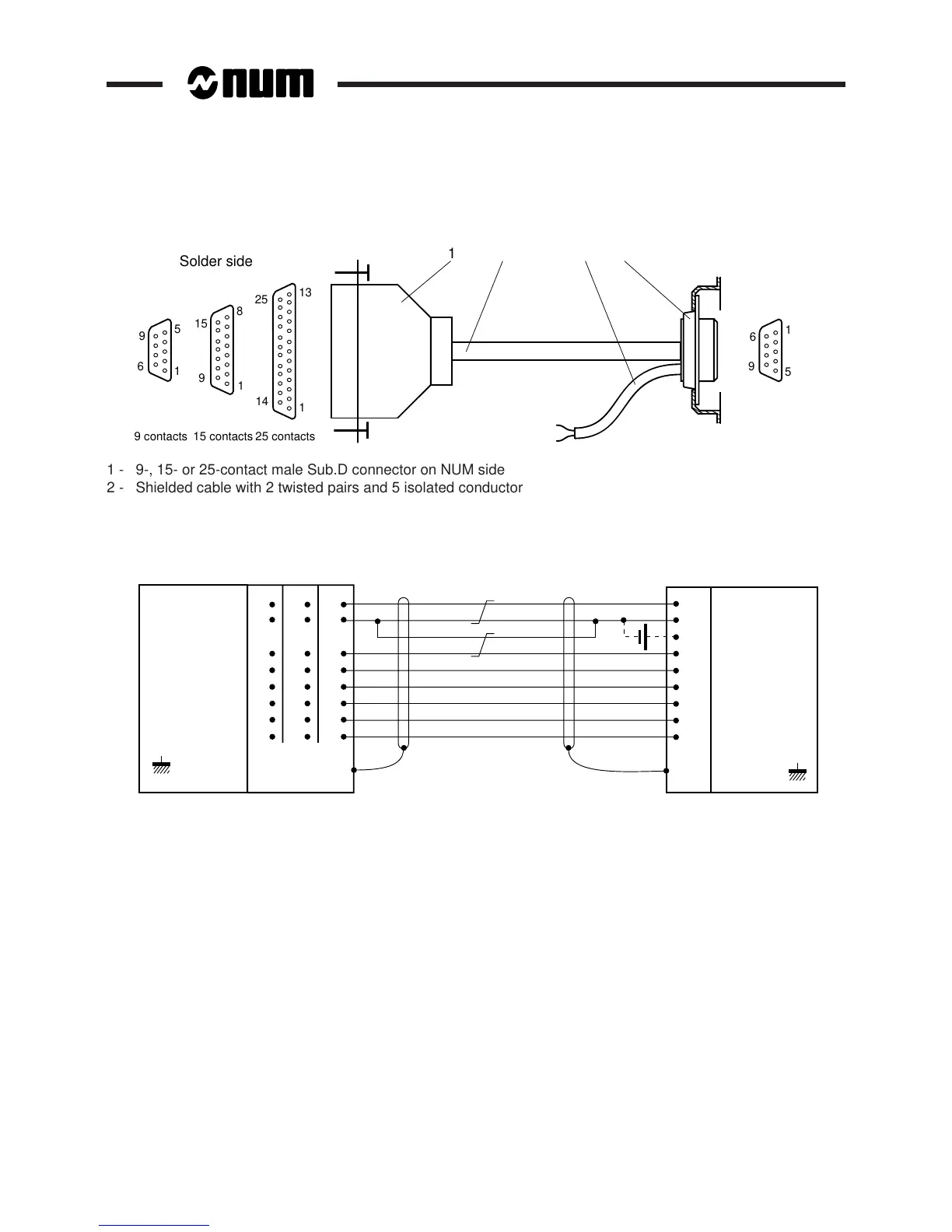
Solder side
1
15 contacts
14
9
6
1
5
9 contacts
8
1
9
15
6
9
5
1
1 - 9-, 15- or 25-contact male Sub.D connector on NUM side
2 - Shielded cable with 2 twisted pairs and 5 isolated conductors (0.14 mm
2
minimum cross sectional area)
3 - 2-wire cable (optional, used for supply of the NUM drive)
4 - Remote 25-contact female Sub.D connector on the compact panel
TD
RTS
CTS
DSR
DCD
0 V
24 VDC
RD
3
7
8
6
1
5
9
2
24 VDC
DTR
4
TD
RD
RTS
CTS
DTR
7
2
3
4
5
20
6
8
DSR
DCD
0 V
5
3
2
7
8
4
∗
6
∗
1
∗
7
1
3
12
5
14
6
13
SUB.D
9 cont. 15 cont. 25 cont.
CONNECTOR
BODY
PROTECTIVE
EARTH
PROTECTIVE
EARTH
CONNECTOR
BODY
∗ Contacts 1, 4 and 6 must not be connected on the 9-contact connector of the V2 machine processor.
REMARK When contact 24 of the remote line is connected to a power supply, the drive must
not be supplied via the jack.