4 - 18 en-938821/2
4.6.2 Machining Simulation
Machining simulation is used to visually check that the programme runs as expected (part dimensions and sequencing
of operations).
Simulated machining is based on real machining performed by the CNC in automatic (See 5.4.3.5) and single step
modes (See 5.4.3.3), but no real axis motion takes place.
Programmed interventions (M00, M12, data input, etc.) are not taken into account during simulation.
External parameters (E) are not modified during simulation.
Requirements
"GRAPHIC - PROGRAMMING" menu displayed (See 4.6).
Scaling of part (See 4.6.1).
Actions
Select plane 1. ☞
!
1
or
Select plane 2. ☞
@
2
Display of the tool path trace (same as trace obtained via the graphic display parameters page (See 4.6.1.2)).
REMARKS If manual scaling is the only operation to have been performed (See 4.6.1.1), the
scaled area is displayed without any trace.
The next part of the procedure can also be accessed using the tool path trace
function in the graphic display parameters page (See 4.6.1.2).
If required, use the ZOOM function to enlarge a path detail. (See 4.6.1.2).
Select the simulation function. ☞
SIMULN.
TRACE
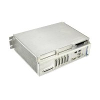
Display of the current position coordinates in the modal data window and the simulated machining softkeys:
EXIT
END
SIMULN.
SINGLE
BLOCK
HOLD
CYCLE
AUTO
MODE
TOOL
PATH
START
CYCLE
STATUS