6
INSTALLATION
(Continued)
Connecting the Power
Transformer
Refer to Figure 11
NOTE: Be sure AC power is off before connecting the
power transformer. DO NOT turn AC power on to
transformer until ALL wiring at the remote and master
stations is complete.
1. The transformer’s primary leads should already be
connected to the 120 volt AC house supply wiring. Be sure
the power is off before connecting the transformer to the
master station.
2. The RED and WHITE low voltage transformer leads are
located in the bottom left corner of the master station.
Connect and tighten these low voltage leads to the
transformer’s low voltage secondary screw terminals
located in the bottom left of the rough-in.
Connecting the Ground Wire
Refer to Figure 11
1. Remove the front #6 transformer box mounting screw from
rough-in.
2. Insert screw into ring terminal of green/yellow ground wire.
3. Reinstall the screw with ring terminal into the same mounting
hole that the screw was previously removed from.
Connecting the Antenna
Refer to Figure 12
1. Plug the AM/FM antenna (supplied with the IR-103 rough-in
frame) to the 2-pin connector located in the upper right
corner of the main circuit board.
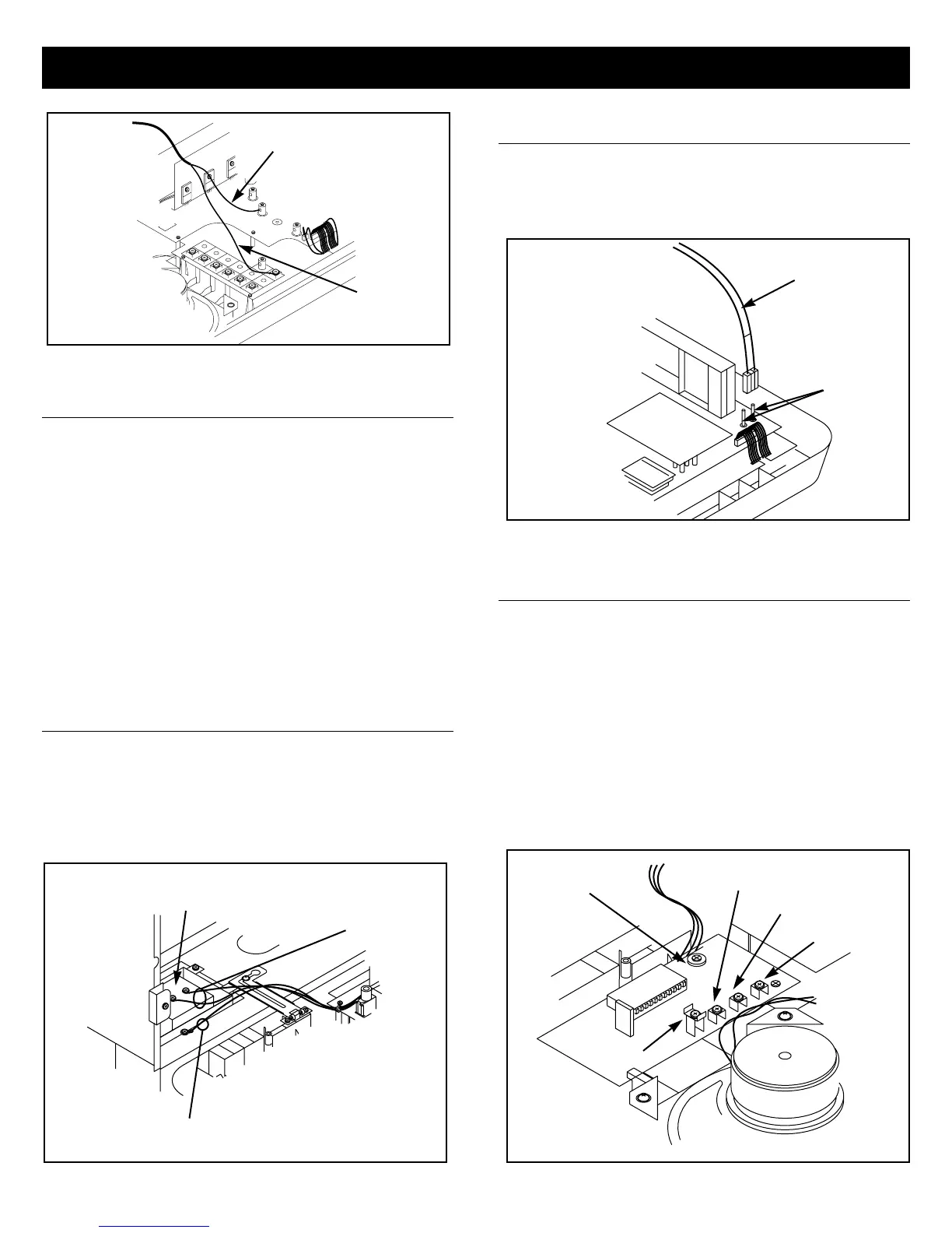
Connecting the Optional
Chime Module
Refer to Figure 13
Refer to the earlier section “Mounting the Optional Chime Module
in the Master Station Panel”.
1. Identify the front chime push button wires. Strip back each
wire approximately 5/8".
2. Connect the front push button wires to the screw terminal
marked FRONT and COMMON on the chime module.
3. Repeat steps 1 and 2 for the REAR and SIDE chime push
buttons.
4. Refer to the instructions packed with the chime module for
information on chime volume level and chime tune selection
(IA-29 only).
FIGURE 11
FIGURE 10
FIGURE 12
FIGURE 13
GRAY WIRE
WHITE WIRE
TRANSFORMER
RED & WHITE
LOW VOLTAGE
TRANSFORMER
LEADS
GREEN/YELLOW
GROUND WIRE
AM/FM
ANTENNA
ANTENNA
PINS
SIDE
REAR
FRONT
COMMON
CHIME VOLUME
CONTROL
 Loading...