
S
Stanley RobinsonJul 29, 2025
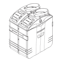
Why is my NuTone PUREPOWER Air Cleaner losing suction?
- SSamantha ArmstrongJul 29, 2025
A loss or decrease of suction in your NuTone Air Cleaner can occur for several reasons. The debris pail or disposable bag might be full, so you should empty it or change the bag. The debris pail gasket could be damaged or missing, requiring a replacement. There might be an obstruction in the hose; try disconnecting the hose and using a flexible garden hose to clear it. The permanent filter or disposable bag may be torn, in which case you should clean the unit and install a new HEPA filter or bag. Also, ensure all wall inlet covers are properly sealed and that the exhaust tubing or vent isn't clogged.