User Interface
BLDC Control Demo User's Guide, Rev. 6, 06/2020
NXP Semiconductors 17
6. User Interface
The application contains the demo application mode to demonstrate the motor rotation. Operate it using
the user button. The Tower System and Freedom boards include a user button associated with the port
interrupt (generated whenever one of the buttons is pressed). At the beginning of the ISR, a simple logic
executes, and the interrupt flag clears. When you press the SW2 button, the demo mode starts; when you
press the same button again, the application stops and transitions back to the STOP state. There is also
an LED indication of the current application state. The green continuous LED indicates that the
application is in the RUN state, the flashing LED indicates the FAULT state, and the LED off (or red
LED) indicates the STOP state.
Control the application using the buttons on the NXP Kinetis V Tower System and Freedom
development boards. Because the HVP platform does not provide any push-buttons to control the
application, the demo mode runs automatically after the HVP board is switched on.
6.1.
Control button
Pressing the control button switches the demo mode on (or switches the demo mode off if it is currently
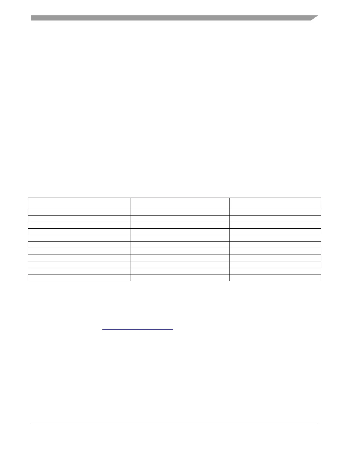
switched on). Table 14 shows the correct switch button for your development board.
Table 12. Control button assignment
Board Control button LED state indication
6.2.
Remote control using FreeMASTER
Remote operation is provided by the FreeMASTER software via the USB interface. FreeMASTER 3.0 is
required for optimal operation of the application. The FreeMASTER 3.0 application installation is
available for download at www.nxp.com/freemaster.
Perform these steps to control a BLDC motor using FreeMASTER:
1. Open the FreeMASTER project file (bldc.pmp) in the
<sdk_package_folder>middleware/motor_control/freemaster folder.
2. Click the communication button (the green “GO!” button in the top left-hand corner) to establish
the communication.