Hardware setup
BLDC Control Demo User's Guide, Rev. 6, 06/2020
8 NXP Semiconductors
4.3.4.
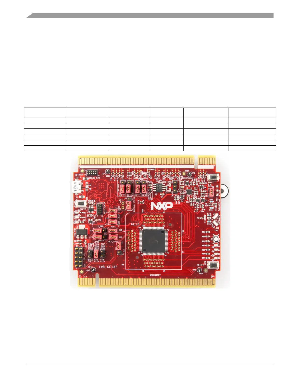
TWR-KE18F Tower System module
The TWR-KE18F is a development tool for the NXP Kinetis KE1x family of MCUs built around the
Arm Cortex-M4 core. This MCU has enough power for use in motor-control applications (such as
PMSM or BLDC motors with simple or advanced control techniques). The MCU has a wide range of
peripherals, lots of memory (depending on the model used), and a powerful core.
To begin, configure the jumpers on the TWR-KE18F and TWR-MC-LV3PH Tower System modules
properly. Table 9 lists the specific jumpers and their settings for the TWR-KE18F Tower System
module.
Table 7. TWR-KE18F jumper settings
Jumper Setting Jumper Setting Jumper Setting
Figure 6. TWR-KE18F Tower System module
4.4.
Tower System assembly
1. Insert the TWR-KVxxXxx MCU module and the TWR-MC-LV3PH module into the
TWR-ELEV card slots. Ensure that the primary sides of the modules (marked by white stripes)
are inserted into the primary elevator card (marked by white connectors).
2. After assembling the Tower System, connect the required cables as follows: