NZXT. 7
Audio Port Installation
1. Please first refer to your motherboard manual and match the
labels on the audio wires with your motherboard pins.
2. The green input is the speaker input and the pink input is the
microphone input.
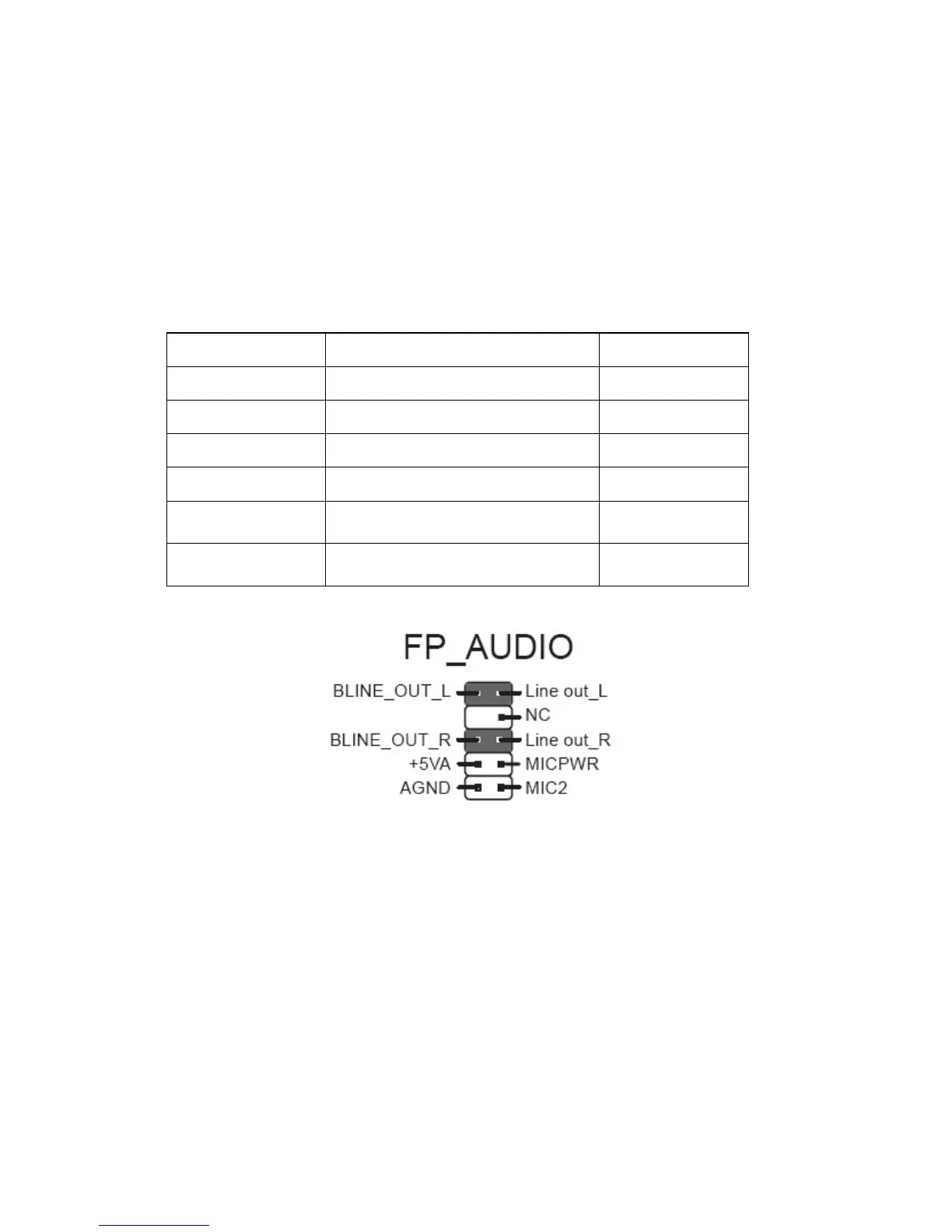
Case Pins Signal Description ASUS© Pins
MIC-IN Front Microphone input Signal MIC2
MIC-POWER Front Microphone Power MICPWR
GROUND Front Audio Ground AGND
L-OUT Front Left Channel Audio Signal Line out_L
R-OUT Front Right Channel Audio Signal Line out_R
L-RET Rear Left Channel Audio Signal
BLINE Line
out_L
R-RET Rear Right Channel Audio Signal
BLINE Line
out_R
ASUS© Motherboard Pin Assignment
External 5.25” Drive Bay Installation [Bays 1-3]
Please follow the directions below to install the 5.25” in the top 3
bays of the Tempest:
1. Remove the front panel of the chassis by pulling from the
opening at the bottom of the front panel.