- 12 -
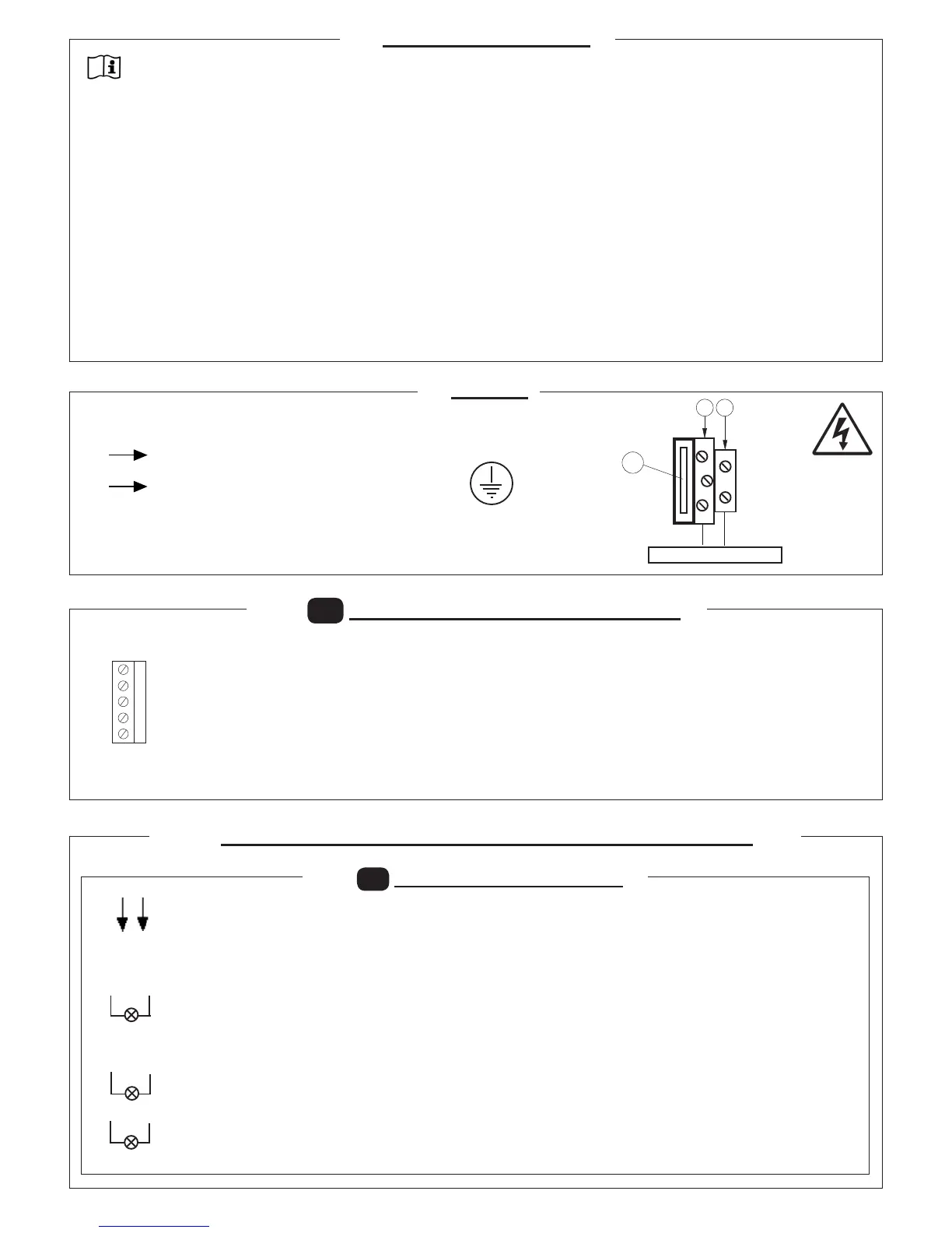
230V LINE
- Transformer input at 230V 50/60Hz
- Connect the earthing pole in the relevant terminal.
- Power the gear motor via the 3-way terminal
protected by 1A fuse (5x20).
- Utilise an H07RN-F 2x1.5+T min type cable
5. POWER
230 V ~
F
N
4. SAFE INSTALLATION
In order to reach the level of safety required by current standards, read the following prescriptions carefully.
Do all the connections on the terminal block, reading the instructions given in this manual carefully and observing the general code of
practice regulating the execution of electrical installations.
Install a four-pole circuit breaker upstream from the installation with a minimum contact opening distance of 3 mm.
Install, wherever it is not foreseen, a differential switch with a 30 mA threshold.
Check effectiveness of the earthing system and connect to it all parts of the automation that have a terminal or earth wire.
There must be at least one signalling device outside, either a trafc light type or a ashing light, together with either a danger or
warning sign.
Apply all the safety devices required by the type of installation, considering the risks it can cause.
Separate the power lines (min. 1,5 mm
2
cross section) from the low voltage signal lines (min. 0,5 mm
2
cross section) in the ducts.
Jumper the unused NC inputs.
Arrange in series any contacts to be connected to the same NC input.
Arrange in parallel the inputs connected to the same NO input.
Keep radio control or other control devices out of children’s reach, in order to avoid any unintentional automation activation.
1)
2)
3)
4)
5)
6)
7)
8)
9)
10)
11)
1A
TRANSFORMER
(230V)
F N
OUT 24V
Accessories power supply (max 12 W):
24 Vac operations with mains power on.
24 Vdc (out+, 24V-) operation with no main power and optional buffer battery kit. KIT-BATT-SC
SCA 24Vac 3W max
Carriageway open LED that ashes slowly during opening, rapidly during closing, remains lit steady during the stop and
pause phase and switches off when the barrier is closed.
N.B.: The indicator lamp ashes twice to indicate that the automation system has detected an obstacle three consecutive
times while closing. Automatic closing is temporarily disabled and is enabled again only after a subsequent successful
closing cycle.
YELLOW FLASHING LAMP (SL-R-24V-AI) 24Vac 25W max.
Flashing output for self-ashing blinker
NOT USED
6.1
M1
POWER TERMINAL BLOCK
MOT1 - MOT2
Motor output 24Vdc. After a power failure, the rst action performed is an opening cycle.
If it fails, stop the automation, take the motor connector out and put it back in the other way around.
TRAS1 - TRAS2
24 Vac input for transformer. Connection to the control unit
is shown in the gure here
+ACC
Do not use
5.1
M3
MOTOR + POWER SUPPLY 24 Vac
6. INPUT AND OUTPUT CONNECTIONS AND FUNCTIONS
OUT 2
OUT 1
+ACC
TRAS 2
TRAS 1
MOT2
MOT1
OUT 24V
OUT 3
-
+
 Loading...