C: Specifications
22 270-00000-000-02-0108
20-Pin Accessory Connector Pinout
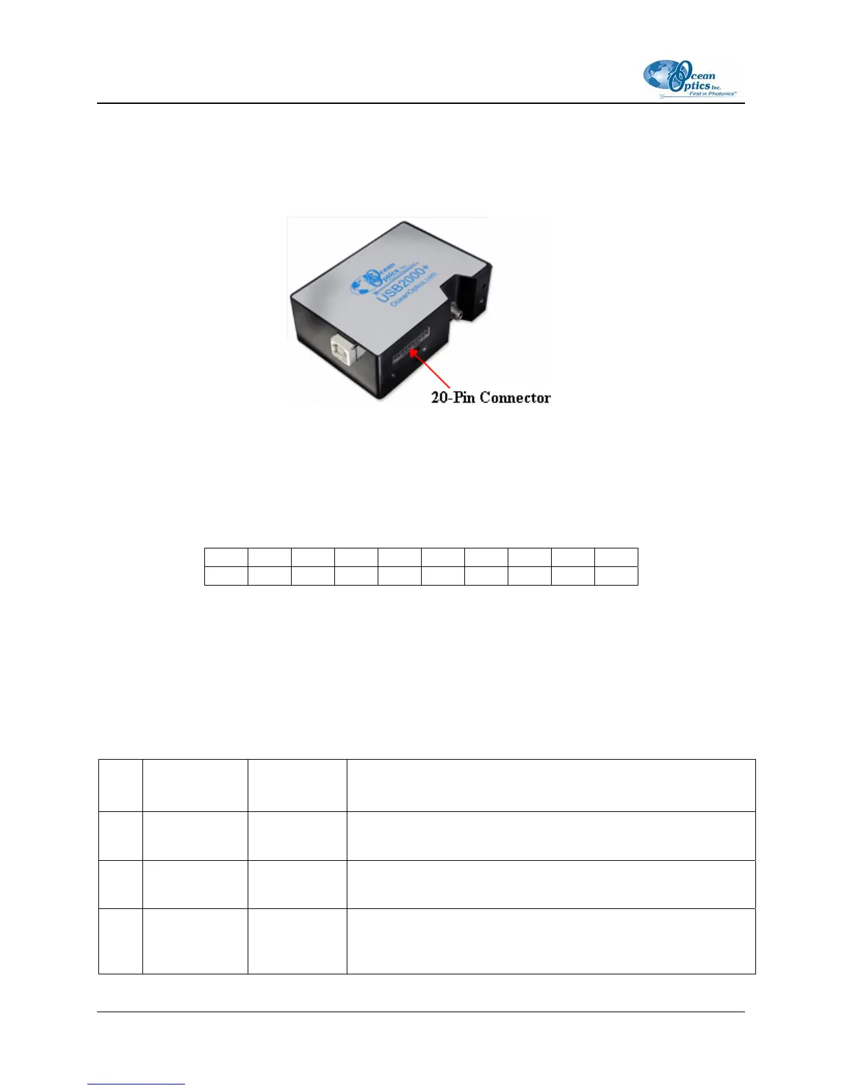
The USB2000+ features a 20-pin Accessory Connector, located on the front of the unit as shown:
Location of USB2000+ 20-Pin Accessory Connector
20-Pin Accessory Connector Pinout Diagram
When facing the 20-pin Accessory Connector on the front of the vertical wall of the USB2000+, pin
numbering is as follows:
18 16 14 12 10 8 6 4 2 A2
17 15 13 11 9 7 5 3 1 A1
20-Pin Accessory Connector Pinout Diagram
20-Pin Accessory Connector – Pin Definitions and
Descriptions
The following table contains information regarding the function of each pin in the USB2000+’s 10-Pin
Accessory Connector:
Pin
#
Function Input/Output Description
A1 SPI_CLK Output
The SPI Clock signal for communications to other SPI
peripherals
A2 SPICS_OUT Output
The SPI Chip/Device Select signal for communications to other
SPI peripherals
1
V
CC
, V
USB
, or
5V
IN
Input or
Output
Input power pin for USB2000+ – When operating via USB, this
pin can power other peripherals – Ensure that peripherals
comply with USB specifications