EasyManuals Logo

Octagon TRAX-10 User Manual

Octagon TRAX-10
17 pages
To Next Page IconTo Next Page
To Previous Page IconTo Previous Page
Page #12 background imageLoading...
Page #12 background image
© 2016 Octagon Systems Corporation Page 12 of 17
Mating Connectors
Table 2 – TRAX-10 Mating Connectors
External Connectors
Function
Mating Connector
GPS antenna
TNC-F, 50
Wireless Accessory (optional)
N-F, 50
Wireless WAN (optional)
N-F, 50
Power Input
PT06E12-3SSR or similar
Display Video, Audio, USB PT06E14-19PSR or similar
LAN
PT06E10-6PSR or similar
COM ports, USB
PT06E14-18PSR or similar
Digital I/O & Option
PT06E12-10PSR or similar
CAN Bus
PT06E10-6SSR or similar
Ethernet (rear) Gb Ethernet x 4 M12-x coded
External Connector Pin-outs
The following descriptions are as seen from the outside of the faceplate.
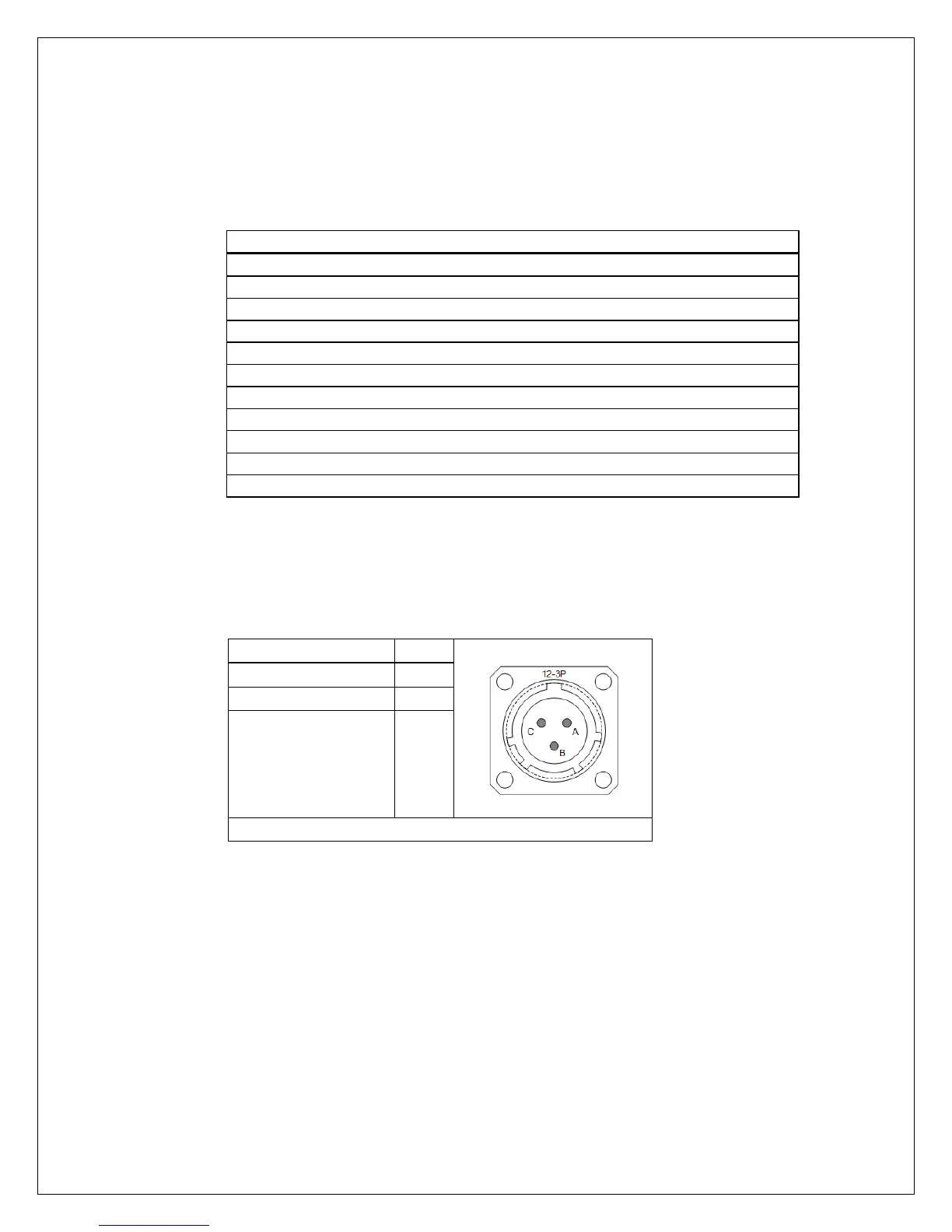
Table 3 - POWER Connector Pin-Out
Signal Name
Pin #
PT02E1203P
V_IN (Voltage IN)
A
GND_EXT (Ext Gnd)
B
IGNITION C
Mating Connector PT06E12-3SSR
The external power cable must be at least 16AWG for cables of 2M or shorter. For
longer cables, use 14AWG. The Ignition Detect signal controls the power management
Suspend and Resume functions; this signal should be connected to the vehicle ignition.
This wire may be as small as 18AWG.

Questions and Answers:

Question and Answer IconNeed help?

Do you have a question about the Octagon TRAX-10 and is the answer not in the manual?

Octagon TRAX-10 Specifications

General IconGeneral
BrandOctagon
ModelTRAX-10
CategoryServer
LanguageEnglish