© 2016 Octagon Systems Corporation Page 6 of 17
Recommended Installation Practices
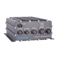
The TRAX-10 is designed to operate in difficult environments. Proper installation will help ensure
product longevity and adherence to the product standards.
1. System should be connected to the vehicle frame via an earthing or grounding bolt on the
rear of the enclosure. A 14AWG (3.31mm
2) stranded wire should be used to connect this
stud to a suitable chassis grounding point. This wire should be as short as possible. The
inclusion of an internal star washer is recommended. This provides some ground-fault
protection and reduces EMI to meet CE requirements.
2. For tracked vehicles, shock mounting would be prudent.
3. Opening the unit must not be done in the field, but at an approved antistatic workstation.
The unit may be opened to replace/install wireless and/or SIM cards. Instructions for
opening the case are available from Octagon Technical Support.
4. The unit should be mounted so as to not impede the convection cooling. Vertical mount is
preferable. It is strongly recommended that the space between the heat fins and other
objects exceed 100 mm (4”) and there is at least 50 mm (2”) of open space on the other
sides. Avoid “dead air” spaces such as under seats. The unit should not be bolted to any
surface that is hotter than the ambient air surrounding the unit.
5. The protective caps must be left on all unused connectors. Failure to do so may render
those connectors unusable in the future due to corrosive liquids or conductive dust.
6. There are no internal repairable components. Customer field repair is in violation of
Octagon’s warranty.
7. Do not over-tighten the antenna cable connectors.
8. The TRAX-10 includes mounting flanges that must be secured to a surface with ¼ inch or 6
mm bolts or screws.
9. The power supply cable gauge should be as large and as short in as practicable.
10. The TRAX-10 is protected against transient voltages common in mobile applications. It is
recommended that external in-line fuses be used on both input power lines. Octagon
recommends standard, fast acting 10A fuses.
11. Proper ESD precautions and method must be followed when installing, servicing, or
otherwise handling the TRAX-10.
12. The USB 2.0 has a maximum cable length of 5M. Cables with built-in repeaters to extend
this length should not be used.
13. The TRAX-10 contains several switching regulators with an inrush requirement of 10A. The
external supply must be capable of supplying this inrush current so as to not “starve” the
startup of the internal supplies. If the power supply is mounted remotely to the TRAX-10,
the wiring size must be increased to prevent excessive drop during startup.
14. Contact Octagon Technical Support for proper disassembly/ access to internal options &
expansion. Storage options must be factory installed.
15. To power down the TRAX-10, turn the ignition switch off. Allow two minutes for the
automatic shut-down sequence (saving data and configuration) to complete. The LED on
the display will go off signaling the completion.
16. High pressure, power washing is prohibited
Warning – During Arc welding/Electrical Resistance welding on the vehicle in which
this product is installed, EVERY and ALL cables to the unit must be disconnected
prior to welding. Otherwise the unit may be seriously damaged and the warranty is
VOID.
 Loading...