Page 3 of 6
For Reference Only
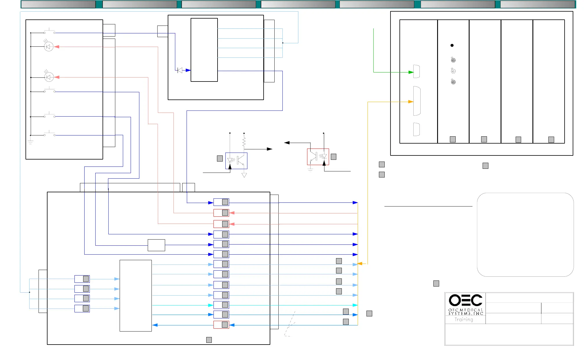
FRAME STORE CONTROL (B104 Rev B)
COMPACT 7600
IMAGE SYSTEM
3/12/97
IMAGE_C.DS4
CPU-100 NWA-500
BSA-500C
BSA-500
S2
S3
S4
Serial
Port
Parallel
Port
Not
Used
Reset Switch
SV
L3
L2
BMS-500 FRAME STORE
From Patient
Annotation
Keyboard
VME 68000 PROCESSOR
SCAN CONVERTER
(60HZ TO 120HZ)
MEMORY
(LAST IMAGE HOLD PLUS 3 STORED IMAGES)
FRAME GRABBER
ALU
A:D
S22
S101
S36
LED 22
LED 37
-KMIR
(Reversal)
+LEDMIR
(Reversal)
S37
-KENH
(Auto Window)
+LEDENH
(Auto Window)
-KSAFE
(Save)
-KUP
(Increment Memory)
CONTROL PANEL
ST104
ST1
40
3
8
10
5
6
CONTROL
LOGIC
PAL U1
PAL U2
PAL U3
PAL U27
and
associated
support
gates
-KMIR
ST2
40
ST5
5
B100 BOARD
U4
1
CONTROL
LOGIC
PAL U1
INVERTER U8
OR GATE U12
U3
1
U5
U5
U3
1
U3
1
U6
1
U3
1
U6
1
U6
1
U6
1
U4
1
U7
U12
LOGIC
6
5
B104 REV B BOARD
ST2 6 5 8 10
ST1
5
3
-KMIR
-TRIGOUT
+LEDMIR
+LEDAENH
-KENH
-KSAFE
-KUP
-SAFE
-MIRLED
-ENHLED
-MIR
-ENH
-M+
-M>
-FC0
-FC1
-FC3
-MODE
-TRIGIN
-FC2
12
9
8
11
6
6
14
4
4
14
8
10
16
10
12
14
16
16
-F10
-F11
-F12
-F13
-SETUP
-SPT
-SPR
2
8
6
4
2
2
6
4
ST3
23
12
19
21
10
22
15
3
16
4
8
20
5
Reverse Image Acknowledge
Reverse Image Request
Autowindow Acknowledge
Autowindow Request
Save Image Request
Increment Image Memory
Filter Code Bit 0
Filter Code Bit 1
Filter Code Bit 2
Filter Code Bit 3
Menu Mode Request
Frame Store Enable
Frame Store Ready
Control
Input
+5VS
+5V
1
Control
Output
Control
Output
Control
Input
+5VS
2
2
2
2
FRAME STORE SETUP
QUIT SETUP
LANGUAGE ENGLISH
FRAME FREQUENCY 60HZ
LIVE DELAY 200ms
FILTER CODE SOURCE EXTERN
FILTER STEPS 0
INTERGRATION 0
AUTOWINDOW LIVE
AUTOM. STORE OFF
PRINT TIME 2000ms
IMAGE POSITION 0
MESSAGE LANGUAGE ENGLISH
4 4
4 4
4
See the Frame Store section of the
service manual for jumper configurations
ACCESS FRAME STORE SETUP
1. Press the ’ON’ and ’SAVE’ switches
simultaneously
2. Cycle through menu using the ’M>’ switch
3. Toggle selections using the ’SAVE’ switch
Note: If there are more then two selections
available the message ’NEW VALUE’
will be displayed. You can then use
the ’M>’ switch to change the value.
U2
1
U2
1
U2
1
U2
16
14
12
10
2
4
6
8
-FLUORO REG
-F0
-F1
-F2
11
12
13
14
11
12
13
14
ST1
-FLUORO
REG
-F0
-F1
-F2
-XRY
-PU1
-FM
-PUD
5
5
5
5
1
See Fluoro Mode Diagram
6
6
USE THIS PAGE FOR SYSTEMS WITH B104 REV B BOARDS.
SEE PAGE 2 FOR SYSTEMS WITH B104 REV A BOARDS.
TRIGIN = enables the image processor.
TRIGOUT = from the image processor stays
active, enabling exposure, for 640 msec after
the xray switch is released. This ensures
sufficient time to for last image hold.
7
8
7
8
See charts 1 & 2
page 6 for LED
Status
D1
5
The filter code bits control
the amount of averaging used.
Averaging varies depending
on the operating mode.
See chart 4, page 6
COMPONENT LOCATION
DIAGNOSTICS PARTS FINDER PERSONAL NOTES THEORYREMOVAL - REPLACEMENTCALIBRATION
Used and Refurbished C-Arms are Available from www.SharpMedical.com - Call us at 800-969-9800
An Independent C-Arm Service Provider. This PDF provided for research / historical purposes only.
 Loading...


