Page 2 of 4
For Reference Only
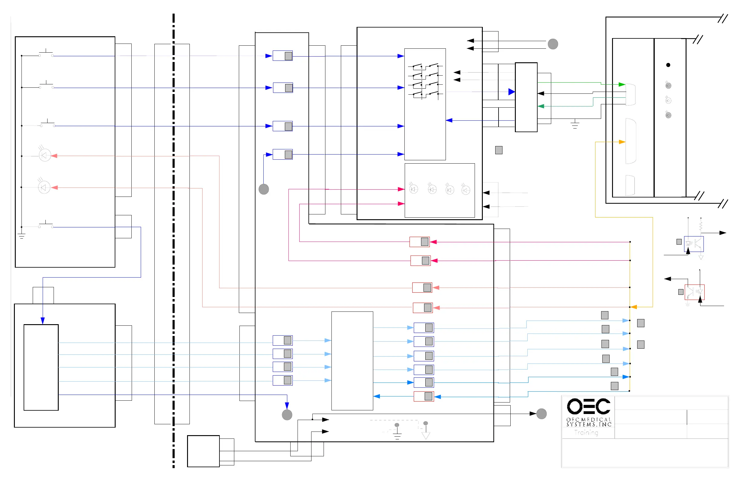
FRAME STORE CONTROL
IMAGE_S.DS4
SERIES 7600
IMAGE SYSTEM
6/24/97
S22
LED 22
-KMIR
(Reversal)
+LEDMIR
(Reversal)
S101
--KSAFE
(SAVE)
+LEDENH
(Auto Window)
B500 CONTROL PANEL
ST104
ST1
40
3
5
10
CONTROL
LOGIC
PAL U1
PAL U2
PAL U3
PAL U27
and
associated
support
gates
-KMIR
ST2
40
ST5
5
B100 BOARD
CONTROL
LOGIC
PAL U1
INVERTER U8
OR GATE U12
U5
U5
U6
1
U3
1
U6
1
U6
1
U6
1
U7
B104 REV B
BOARD
ST2
ST1
-TRIGOUT
+LEDENH
-FC0
-FC1
-FC3
-TRIGIN
-FC2
11
6
10
12
14
16
-F10
-F11
-F12
-F13
-SPT
-SPR
8
6
4
2
4
16
2
ST3
12
19
15
3
16
4
20
5
Filter Code Bit 0
Filter Code Bit 1
Filter Code Bit 2
Filter Code Bit 3
Frame Store Enable
Frame Store Ready
Control
Input
+5VS
+5V
1
Control
Output
Control
Output
Control
Input
+5VS
2
2
2
2
See the theory
section of the
service manual
for Frame Store
jumper
configurations
U2
1
U2
1
U2
1
U2
16
14
12
10
2
4
6
8
-FLUORO REG
-F0
-F1
-F2
11
12
13
14
11
12
13
14
-FLUORO REG
-F0
-F1
-F2
-XRY
-PU1
-FM
-PUD
5
5
5
5
5
The filter code bits control
the amount of averaging used.
Averaging varies depending
on the operating mode.
See chart 4, page 4
1
(See Fluoro Mode Diagram)
TRIGIN = enables the image
processor.
TRIGOUT = from the image
processor stays active, enabling
exposure, for 640 msec after the
xray switch is released. This
ensures sufficient time to for last
image hold.
7
8
7
8
-MIRLED
S36
-KUP
(Increment Memory)
6
S31
LED 31
-ENH
(Auto Window)
8
U5
U5
13
7
2
2
LED Data Clock
LED Serial Data
EDLED
SAFELED
-ENHLED
Reverse Image Acknowledge
Autowindow Acknowledge
C-ARM
WORKSTATION
A
PO CABLE
PO CABLE
15 15
9
9
16 16
17 17
11
11
19
19
20
20
29
29
30 30
13 13
+LEDMIR
10
3
A
U14
1
U14
1
U14
1
U13
1
8
6
4
8
6
5
-KMIR
4
-KMIR
-KMIR
5
ST10
LEDEDIT
LEDSAFE
2
16
6
4
14
8
9
(LED Data Clock)
(LED Serial Data)
10
12
14
14
9
7
4
5
3
8
ST7
KEYBOARD
MATRIX
LOGIC
U1, U2
U5, U7
Switches
LED CONTROL
U8, U9, U10
F1
H5
H6
H7
Auto
Histo
Man
Win
Man
Lev
Man
Lev
-KSAFEIN
-KUPIN
-KENHIN
-KMIRIN
DATA
CLOCK
U5-6
U7-8
U7-6
U7-4
U9-18
U9-8
B550 KEYBOARD
9
7
4
5
3
8
-KSAFE
-KUP
-ENH
COLUMN
4-12
ST8
(9 Lines)
ST1
DECODER BOARD
ROW
1-16
ST9
(16 Lines)
ST2
1-16
4-12
CPU-100
S2
S3
S4
Serial
Port
Parallel
Port
Not
Used
3
1
BMS 100 FRAME STORE
Reset
SV
L3
L2
Switch
2
ST3
B116
POWER
SUPPLY
ST2
ST5
+5VDC
3
1
3
1
+5VDC
-KMIR
+5VDC (VCC)
+5VDC (VCCSYS)
MP2
MP1
Frame Store Control Lines
B
B
14
ST10
+5VDC (VCC)
ST7
14
+5V_104
6
1
2
8
5
TXD
+5VDC
+CTS
See
charts 1 & 2
page 4 for
LED Status
GND_104
+5V
GND
1
1
14 14
ST2
13
16
+5V_108
GND_108
From B108 for
hard copy camera
exposure control
13
Used and Refurbished C-Arms are Available from www.SharpMedical.com - Call us at 800-969-9800
An Independent C-Arm Service Provider. This PDF provided for research / historical purposes only.
 Loading...


