64
Mod.
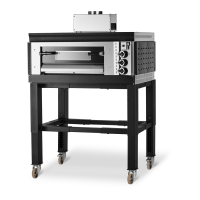
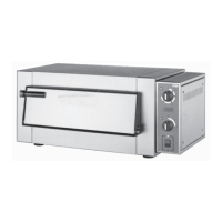
SG69 - 99
Forno a gas
Gas oven
Four à gaz
Gasofen
Horno a gas
MANUALE D'USO E MANUTENZIONE
OPERATING AND SERVICE MANUAL
MODE D’EMPLOI ET D’ENTRETIEN
BEDIENUNGS- UND WARTUNGSHANDBUCH
MANUAL DE USO Y MANTENIMIENTO
Bruciatori della Suola (A - Fig. 17) (centrali)
Si accede agli ugelli come descritto al punto precedente.
Bruciatore Pilota (Fig. 18): Si accede al pilota togliendo il pannello (F).
Per cambiare l’ugello svitare il dado (B - Fig. 18), estrarre l’ugello (C) e sostituirlo secondo la
tabella “DATI TECNICI”.
Bruciatori Interaccensione (Fig. 19): Anche a questi si accede togliendo il pannello
(F). L’ugello interno (E) è così raggiungibile: svitarlo e sostituirlo con quello più adatto secondo la
tabella “DATI TECNICI”.
I
GB
D
F
E
Brûleurs du sol (A - Fig. 17) (centraux)
On accède aux brûleurs selon la description précédente.
Brûleur Pilote (Fig. 18): On accède au pilote en enlevant le panneau (F).
Pour changer le gicleur, dévisser l’écrou (B - Fig. 18), extraire le gicleur (C) et le remplacer
selon le tableau “DONNEES TECHNIQUES”.
Brûleurs inter allumage (Fig. 19): on accède également à ceux-ci en enlevant le
panneau (F). Le gicleur interne (E) est ainsi accessible: le dévisser et le remplacer avec celui qui
est le plus adapté selon le tableau “DONNEES TECHNIQUES”.
Brenner der Sohle (A - Abb. 17) (zentral)
Zu den Düsen erhält man wie im vorstehenden Punkt beschrieben Zugang.
Zündbrenner (Abb. 18): Zum Zündbrenner erhält man durch Abnehmen der Platte (F)
Zugang. Zum Auswechseln der Düse die Mutter (B - Abb. 18) abschrauben, die Düse (C)
herausziehen und gemäß der Tabelle “TECHNISCHE DATEN” auswechseln.
Brenner zur wechselseitigen Einschaltung (Fig. 19): Auch zu diesen erhält man durch
Abnehmen der Platte (F) Zugang. Die innere Düse (E) ist so erreichbar: Abschrauben und gegen
die laut der Tabelle “TECHNISCHE DATEN” am besten geeignete auswechseln.
Bottom burners (A - Fig. 17) (central)
The nozzles are reached as described above.
Pilot burner (Fig. 18): Remove the panel to access the pilot flame (F).
To change the nozzle, undo the nut (B - Fig. 18), take out the nozzle (C) and replace it
according to the “TECHNICAL DATA” table”.
Inter-ignition burners (Fig. 19): These are also accessed by removing the panel (F).
Once the inner nozzle (E) is reached, unscrew it and replace it with a suitable one, according to
the “TECHNICAL DATA” table.
Quemadores de la Solera (A - Fig. 17) (centrales)
Se accede a los toberas como se describe en el punto precedente.
Quemador Piloto (Fig. 18): Se accede al piloto quitando el panel (F).
Para cambiar la tobera desenroscar la tuerca (B - Fig. 18), extraer la tobera (C) y sustituirla
según lo indicado en la tabla “DATOS TECNICOS ”.
Quemadores Interencendido (Fig. 19): También a éstos se accede quitando el panel
(F). La tobera interna (E) es accesible de esta forma: destornillarla y sustituirla con una más
adecuada según la tabla “DATOS TECNICOS”.