© 2016 OJ Electronics A/S
13
INSTRUCTIONS OJ-DV | Installation
Figure 13.10
BR1014A01a
© 2015 OJ Electronic A/S
1
1
2
BBR1014A01a
Figure 13.11
BR1014A03c
© 2016 OJ Electronics A/S
OJ-DV
-GB
L1
L2
L3
PE
L1
L2
L3
PE
-V+
-Add. Pin1
-Bus B
-Bus A
-Gnd
-Add. Pin2
-Add. Pin1
-Bus B
-Bus A
-Gnd
-Add. Pin2
-V+
-Gnd
-Bus B
-Bus A
-Gnd
-V+
A
C
B
+10Vdc
0-10Vin
Gnd
Din2
Din1
Dout1
Gnd
A
B
Gnd
U
V
W
PE
U
V
W
PE
BR-
BR+
PE
Motor
Modbus
3-Phase
connection
RJ12 Modbus Slave
RJ12 Modbus Slave
RJ12 Modbus Master
e.g. PTH/VOC
Open
collector
Future use
BR1014A03c
Adr.Pin1
Adr.Pin2
Adr.Pin1
Adr.Pin2
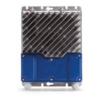
13.10 Spring terminals
• If multi-core cables/leads are used, core sleeves/
end sleeves must always be used.
• The connection terminals are spring loaded and
the stripped wire can be easily inserted into the
terminal by carefully pushing the wire into the
terminal without using tools. Alternatively, the
terminal spring can be loosened by pressing it
lightly with a screwdriver or similar implement. See
fig. 13.10.
• Solid and multi-core cables/leads can be used.
• Stripped wire ends or end sleeves must be
between 8 and 15 mm.
• Wires can be removed by carefully loosening
the terminal spring by pressing lightly with a
screwdriver or similar implement. See fig. 13.10.
13.11 Terminal and connector overview
Figure 13.12
BR1014A09a
© 2015 OJ Electronic A/S
8-15mm
U
VW
PE
Motor
BR- BR+
BR1014A09a
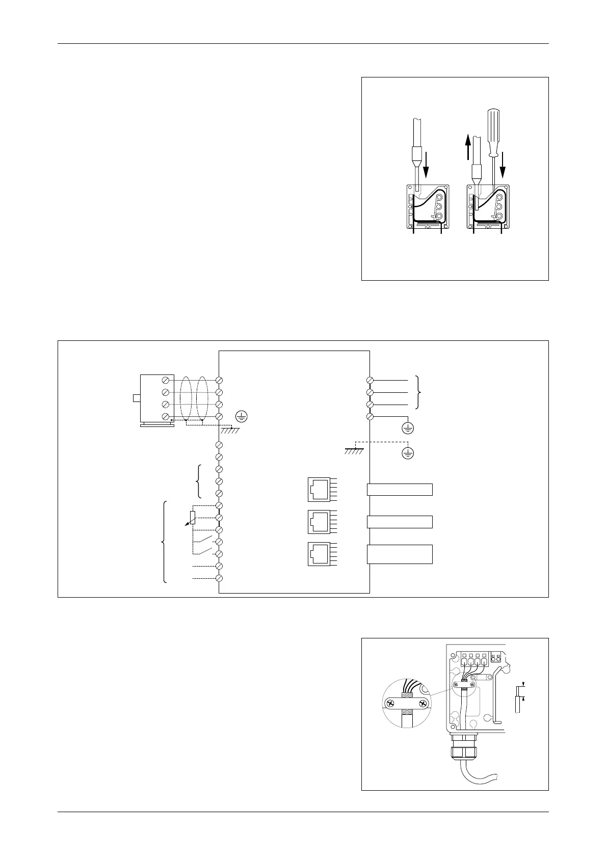
13.12 Motor connection
• The motor cable must be connected to the
terminals marked ”U”, ”V”, ”W” and ”PE”.
• When the stripped wire is properly inserted into
the terminal (see section 13.10), the terminal
tensions automatically with the correct torque.
• IMPORTANT! The motor cable must always be
a shielded cable and the shield must be ended
in the clamp intended for that purpose. See fig.
13.12.
• Remember to re-tighten the cable glands to
ensure ingress protection and strain relief.