© 2016 OJ Electronics A/S
9
INSTRUCTIONS OJ-DV | Installation
12. Mechanical installation
Incorrect mechanical installation may cause overheating and impaired performance.
• OJ-DV must only be installed by trained/experienced personnel.
• To ensure proper cooling of the OJ-DV, it must be positioned in such a way that the passing air
flow (> 3 m/s turbulent air speed) can cool the OJ-DV cooling fins. (3 m/s turbulent air speed is
equivalent to 6.5 m/s laminar air speed). If the OJ-DV is installed in a reduced air flow (< 3 m/s
turbulent air speed) or mounted outside a direct airstream, the output power (kW) will be reduced.
External on-board cooling fan can be added.
• Only OJ-DV-1013 can be installed without considering the above requirements for sucient air
flow over the cooling fins. OJ-DV-1013 is supplied with extra large cooling fins and can therefore
be mounted in still air with an air temperature of max. 40°C.
See Section 25: Technical Specifications.
• To facilitate future service and maintenance tasks, ensure that there is sucient space around the
unit after it has been installed.
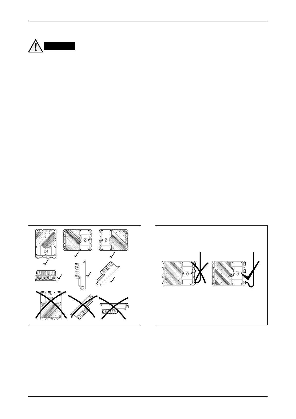
• To achieve the specified enclosure rating, the cable glands must not point upwards (see fig. 12.4).
• To prevent water from entering OJ-DV via cables and cable glands, ensure that connection is
performed in such a way that water is prevented from accumulating around the cable in the gland.
See fig. 12.5.
• Check that the surface to which OJ-DV is attached is capable of supporting the entire weight of
the unit.
• OJ-DV can be mounted vertically, horizontally or at an incline. See fig. 12.4.
• OJ-DV must be installed on a flat solid surface.
• To avoid unnecessarily long motor cables (max. 5 m), OJ-DV should be installed as close to the
motor as possible.
• Use only the pre-cut installation holes/screw holes to secure OJ-DV in place.
• Dimensioned drawings, see figs 11.2 to 11.6.
Warning
Figure 12.4
BR1014A05a
© 2015 OJ Electronics A/S
BR1014A05a
Figure 12.5
BR1014A26a
© 2015 OJ Electronics A/S
BR1014A26a