© 2016 OJ Electronics A/S
15
INSTRUCTIONS OJ-DV | Installation
Note
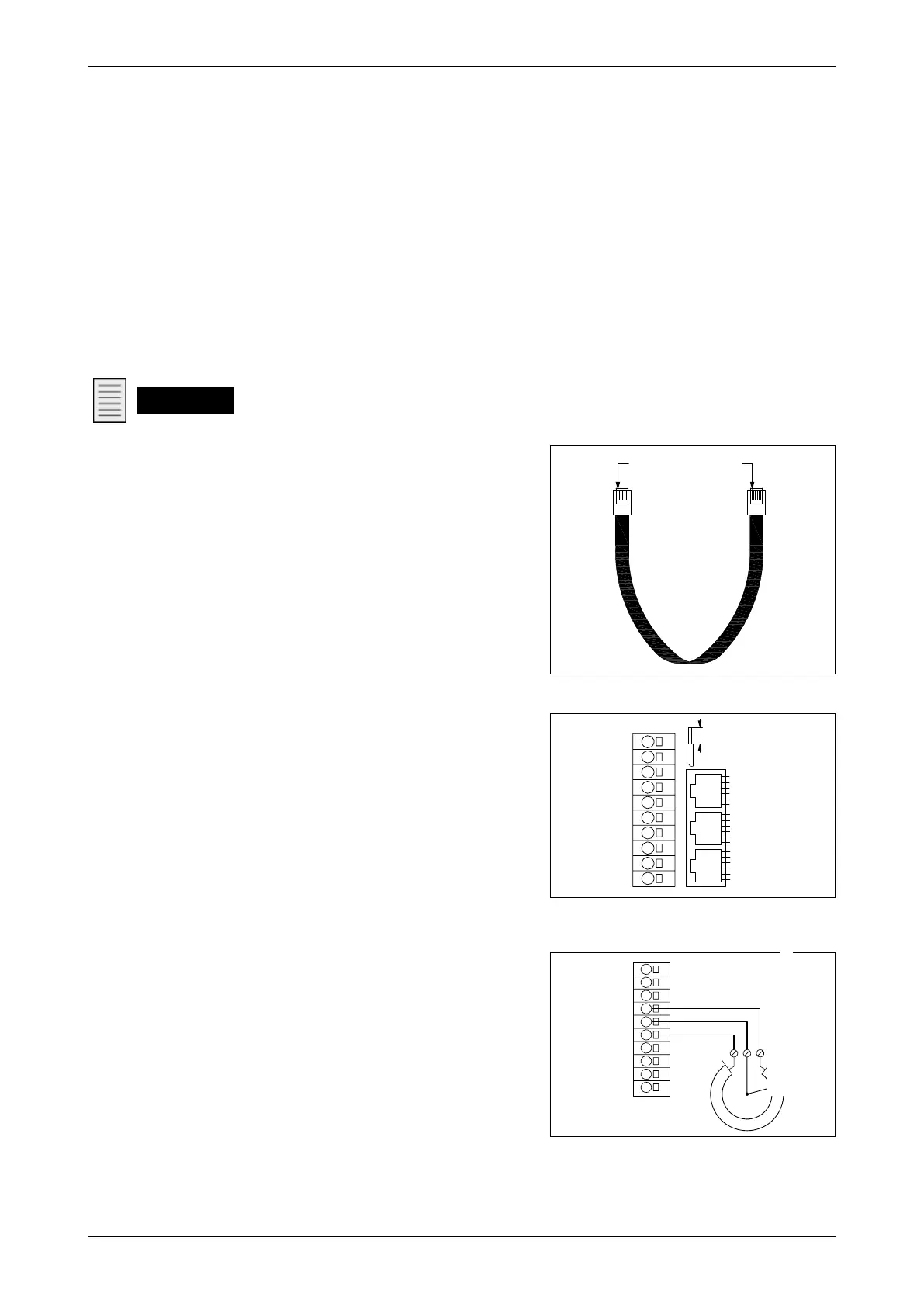
IMPORTANT! RJ12 connectors must be fitted to the ends
in such a way that both connectors have the same colour
sequence as the cable.
See fig. 13.14.2.
13.15 A/D control signal connections
• Connect A/D control signals to the terminal strip,
see fig. 13.15.1
• For further information on using the spring
terminals, see section 13.10.
• The function/programming of A/D inputs and
outputs can be changed via Modbus.
For further information on the Modbus protocol,
contact OJ Electronics A/S
• +10Vdc = Constant + 10 VDC for control signal
and NOT intended as power supply for other
purposes.
• Short-circuit proof also short-circuit between
+24 VDC and +10 VDC
• Tolerance ± 3%
• 0-10V In = Analogue 0-10V control input for
speed
• Potentiometer, electrical connection, see fig.
13.15.2.
Figure 13.15.1
BR1014A15a
© 2015 OJ Electronics A/S
-V+
-Add. Pin1
-Bus B
-Bus A
-Gnd
-Add. Pin2
-Add. Pin1
-Bus B
-Bus A
-Gnd
-Add. Pin2
-V+
-Gnd
-Bus B
-Bus A
-Gnd
-V+
A
C
B
GND
Dout1
Din1
Din2
GND
0-10V In
+10Vdc
GND
Bus A
Bus B
8-15mm
-
BR1014A15a
Figure 13.14.2
BR1014A02a
© 2015 OJ Electronic A/S
Samme farverækkefølge
BR1014A02a
Same colour sequence
• ”B”: Modbus connection, slave, no +24 V voltage in connector.
• ”C”: Modbus connection, Master, external equipment, e.g. PTH/VOC. See fig. 13.11.
• A 6-core, unshielded, 30 AWG/0.066 mm² telecommunications cable or similar type of ribbon
cable can also be used for Modbus communication.
• Attach RJ12 connectors to both ends using a special-purpose tool.
• The OJ-DV is prepared to be installed in Modbus networks either in daisy chain or star
networks. Every OJ-DV has a preinstalled Modbus termination resistor of size 1 kΩ, which in
most applications would be sucient.
• Extra Modbus termination resistor is not to be used, except in installations where the Modbus
exceeds >100 m in a daisy chain Modbus connection.
• If the Modbus exceeds >100 m, it might be necessary to install an extra Modbus termination
resistor of size 180 Ω. This resistor is only to be installed in the last OJ-DV in the chain.
• In Modbus star connection installations, a Modbus termination resistor is mostly not to be used.
BR1014A20a
© 2015 OJ Electronics A/S
GND
Dout1
Din1
Din2
GND
0-10V In
+10Vdc
GND
Bus A
Bus B
BR1014A20a
Figure 13.15.2