© 2016 OJ Electronics A/S
24
INSTRUCTIONS OJ-DV | Maintenance and troubleshooting
Figure 18.5
BR1014A06a
© 2015 OJ Electronic A/S
LED
BR1014A06a
LED indications
• OJ-DV is equipped with a two-colour LED which
indicates operating status.
• The LED is located on the underside of OJ-DV
beside the entry for the mains cable.
See fig. 18.5.
• Lights constantly green when mains voltage is
connected
• Flashes green when Modbus communication is
active
• Lights constantly red when at least one critical
alarm is active
• Flashes red when at least one non-critical
alarm is active
21. Modbus addressing of OJ-DV
Modbus addressing of OJ-DV can be accomplished in two dierent ways.
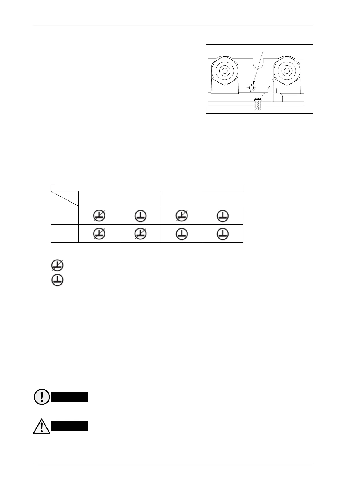
• Via the addressing pins of the ”A” or ”B” connectors – see fig. 13.14.1 and table 20.1.
= No connection between ”GND” and Add.Pin1/ Add.Pin2
= Connection between ”GND” and Add.Pin1/ Add.Pin2
• Via OJ-DV PCTool, where OJ-DV can be set to other Modbus addresses – see instructions for OJ-
DV PCTool.
Modbus protocol
• Contact OJ Electronics A/S if you require a complete Modbus protocol.
22. Maintenance
22.1. OJ-DV is maintenance free under normal operating conditions and load profiles.
22.2. The cooling fins must be kept free of dust, dirt and other foreign matter so that air can pass freely
over them. Deposits of dust, dirt or other foreign matter on and between the cooling fins will prevent
cooling of the OJ-DV and thus impair performance.
Caution
22.3. The cooling fins may become very hot. (Max. 95°C under normal operating conditions.)
Warning
22.4. OJ-DV cannot be repaired on site. Never attempt to repair a defective unit. Contact your supplier to
obtain a replacement.
22.5. Additional technical data are available on request from OJ Electronics A/S.
Table 20.1
Add.
Pin. no.
0X36 (54 dec) 0X37 (55 dec) 0X38 (56 dec) 0X39 (57 dec)
Add.Pin1
Add.Pin2