© 2016 OJ Electronics A/S
23
INSTRUCTIONS OJ-DV | Alarms
• The alarm can be reset by means of a Modbus command.
• The alarm is automatically reset if the power is disconnected for longer than 60 seconds.
• Alarms can be read via Modbus, see Modbus protocol.
• Alarm overview, see table 20.
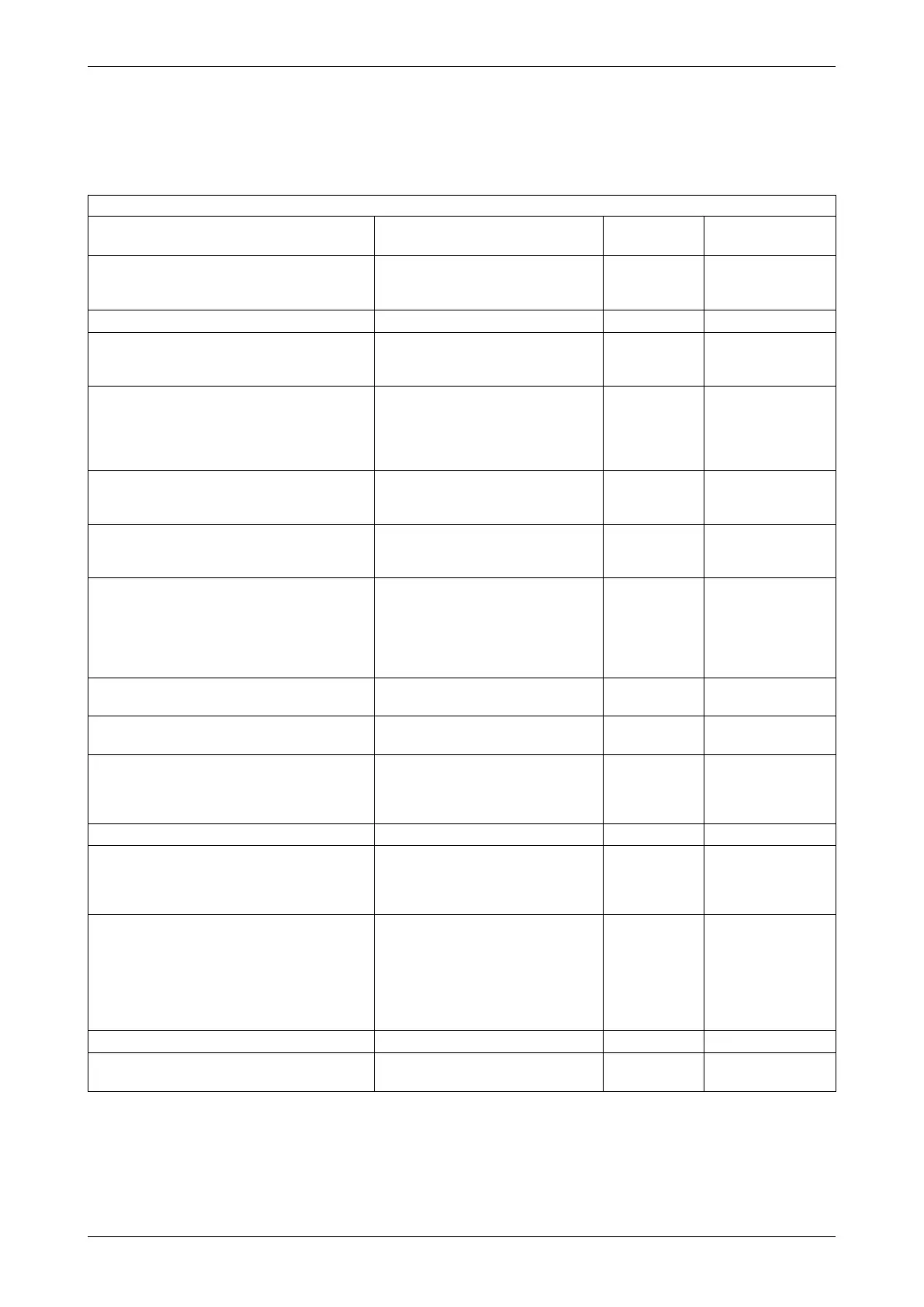
Table 20
Alarm overview Trigger Alarm priority Motor operation/
response
Supply voltage too low
✓ Supply voltage to OJ-DV is too low.
✓ OJ-DV is mistakenly connected to
mains voltage 3 x 230VAC.
”NC” ”RP”
Supply voltage too high
✓ Supply voltage to OJ-DV is too high.
”C” ”SA5”
The motor’s power use is too high
✓ Short circuit in motor cable.
✓ Short circuit in one or more motor
windings.
”C” ”SA5”
Internal temperature in OJ-DV too high (>95 °C)
✓ Cooling of OJ-DV enclosure too low.
✓ Insucient air circulation around
OJ-DV.
✓ Air temperature around OJ-DV is
too high.
”NC” ”RP”
Phase error; one or more phases disconnected
(L1, L2, L3)
✓ Missing phase in supply voltage to
OJ-DV
✓ Large imbalance in supply voltage.
”C” ”SA5”
Blocked rotor
✓ The rotor is unable to rotate due to
a mechanical blockage of the rotor
or fan.
”C” ”SA5”
Motor power has reached it’s limit
✓ OJ-DV has reached the limit for
maximum output power.
✓ The connected motor is larger than
allowed for the chosen OJ-DV
✓ The load is too big for the
connected motor.
”NC” ”RP”
Earth fault
(Only OJ-DV-3110 & OJ-DV-3150)
✓ Earth fault on motor cables or motor
windings
”C” ”SA5”
Running in the wrong direction
✓ Windmilling in the opposite direction
during the start up process.
”C” ”SA5”
Fault in internal EEPROM circuit
✓ Incorrectly chosen configuration file
- tried to download a configuration
file which is not contained in OJ-DV
✓ OJ-DV is defective.
”NC” ”RP”
Stopped after 5 re-start attempts within 60min N/A
”C” ”S”
Phase error in motor supply (U, V, W)
✓ One or more motor phases / motor
cables is disconnected.
✓ One or more motor windings is
disconnected.
”C” ”SA5”
Internal communication fault
✓ During the process of updating
the MOC configuration file,
communication was inadvertently
disconnected.
✓ If the alarm goes o during normal
operation, it usually indicates a
defective OJ-DV.
”C” ”SA5”
Ripple voltage too high
✓ Imbalance on voltage supply.
”NC” ”RP”
External 24VDC supply overloaded.
✓ Overloading or short circuit on +24V
voltage supply.
”NC” ”RP”
Abbreviations:
”C”=Critical alarm
”NC”=Non-critical alarm
”RP”=Reduced performance
”SA5”=Motor stops after 5 restarts caused by same fault within 60 min
”S”=Motor stops immediately