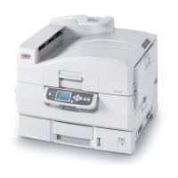
In the left rear corner of the duct support
tray there is a 2 wire connector. Gently
pull the purple & white connector and set it
aside.
NOTE: A C941 has 3 connectors in this
position that must be unplugged.
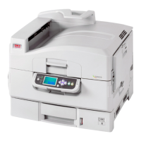
Grasp the duct support tray and gently lift
it up. You will need to flex the black plastic
cover on the right front edge of the frame
to clear it.
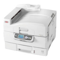
Lift the duct support tray until the tabs at
the rear of the duct support tray clear the
printer frame. At this point the duct
support tray can be removed.
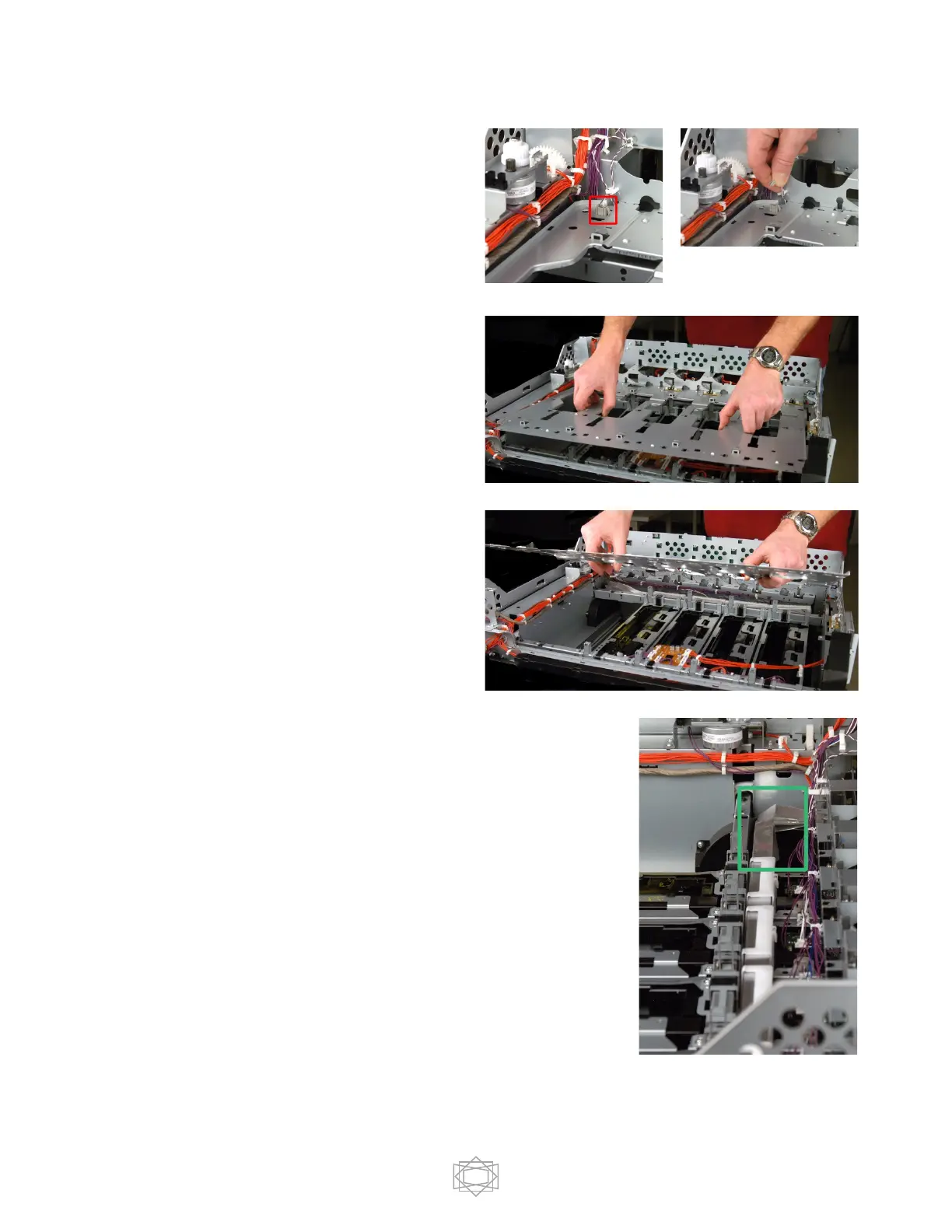
The green highlighted area shows the LED
Print Head cables and the bend they take
to pass through the frame and into the PU
/ CU Board area. It also shows the cable
supports as they run under the duct
support tray and to the LED Print Head
assemblies.
NOTE: The LED Print Head Cable
connectors are fragile. The following page
shows how to successfully release the LED
Print Head / PU / CU Board cable
connectors. Be Very Careful when
unplugging and plugging these cables into
the connectors. Any contacts removed will
create Fatal Errors and require
replacement of the LED Print Head cable.

 Loading...