Do you have a question about the Okolab UNO-T and is the answer not in the manual?
Explains symbols used within the manual for warnings, cautions, and helpful suggestions.
Identifies symbols found on the product, indicating compliance, production date, and manufacturer.
Critical instructions and warnings for safe operation and handling of the equipment, covering usage and transport.
Warnings about electrical hazards, liquid exposure, and general environmental precautions for safe operation.
Details the components and connections for the basic UNO-T incubator system.
Details the components and connections for the premixed gas UNO-T-H-PREMIXED system.
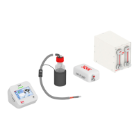
Details the components and connections for the CO2 gas UNO-T-H-CO2 system.
Lists compatible Okolab H301 incubating chambers and their specific stage fits.
Information on compatibility with OBJ-COLLAR and DATA-LOG software.
Describes the ports and indicators on the Left, Rear, and Front panels of the UNO-CONTROLLER.
Step-by-step guide to connect the chamber base and lid to the UNO-CONTROLLER using provided cables.
Instructions for installing the GF-MIXER-HM Humidity Module, including assembly and filling.
Detailed steps for connecting premixed gas and CO2/air gas supplies for different configurations.
Instructions for connecting the T Sensor, optional OBJ-COLLAR, and USB/RS232 communication ports.
Overview of the homepage, status indicators, and navigation icons on the controller display.
Accessing settings, configuring control modes (Chamber/Sample), and chamber/insert options.
Procedures for calibrating objective heater, humidity, sensors, and chamber, plus logging and alarms.
Configuring display options, brightness, date/time, visual effects, and system resets.
Viewing system status, changing display modes, and accessing the info page for system details.
Detailed technical specifications for the UNO-T configuration, including temperature, power, and dimensions.
Detailed technical specifications for the UNO-T-H-PREMIXED configuration, including gas and humidity.
Detailed technical specifications for the UNO-T-H-CO2 configuration, including gas mixture and OKO-AP.
| Brand | Okolab |
|---|---|
| Model | UNO-T |
| Category | Laboratory Equipment |
| Language | English |