13
REMARK
The detectors can be supplied with power either via the MX48 unit or by an auxiliary 24 V DC
source.
These detectors can operate in standalone mode:
24 V DC power supply and direct utilization of relay contacts in accordance with the
technical specification corresponding to the detector used.
The current commercial designations are as follows:
- model 20/20 U - analog - type UV - 752002 (sensitive to UV radiation)
- model 20/20 UC - analog - type UV (sensitive to UV radiation)
- model 20/20 UB - µP technology - type UV - 772002 (sensitive to UV radiation)
- model 20/20 UBC - µP technology - type UV (sensitive to UV radiation)
- model 20/20 LC - analog - type UV/IR (pyroelectric, combination of UV and IR
detectors)
- model 20/20 LBC - µP technology - type UV/IR (pyroelectric, combination of UV and
IR detectors)
- model 20/20 I - µP technology - triple IR detector - 780002 (pyroelectric, sensitive to IR
radiation)
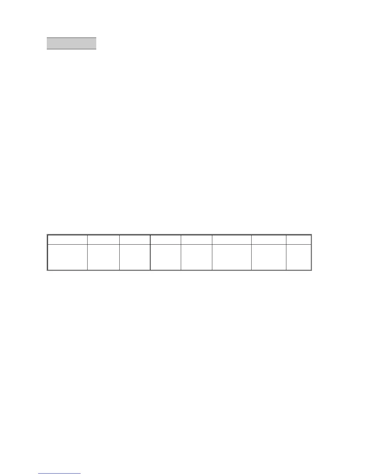
These detectors are equipped with various types of terminal block (see table below).
Model 20/20 U 20/20 UC 20/20 UB 20/20 LC 20/20 UNC 20/20 LBC 20/20 I
Type
of terminal
block
B
C
A
C
C
C
A
- Resistance of cable / unit
- In the case of local 24 V DC power supply:
8.5 ohms maximum per wire, i.e. 17 ohms in loop
- In the case of power supply via the MX48 unit:
3 ohms maximum per wire, i.e. 6 ohms * in loop
∗ 4 ohms for detector 20/20 I (IR3)
- Connection on MX48 unit (ONE detector per measuring channel ONLY):
- detector equipped with a terminal block of type A: see Fig. 13
- detector equipped with a terminal block of type B: see Fig. 14
- detector equipped with a terminal block of type C: see Fig. 15
Example of the utilization of the 4-20 mA signal from flame detectors equipped with connectors of
type A or C: see Fig. 16.
Example of the utilization of detectors equipped with connectors of either type A or type B and with
auxiliary power supply. The auxiliary power supply must be able to supply power to the number of
detectors planned in the measuring loop (see Fig. 17).