14
REMARK
In the case of this application, the maximum of five flame detectors can be connected in the
measuring loop.
Example of the utilization of IR3 or UV/IR detectors equipped with connectors of type A with a
local junction box and galvanic insulation (see Fig. 18).
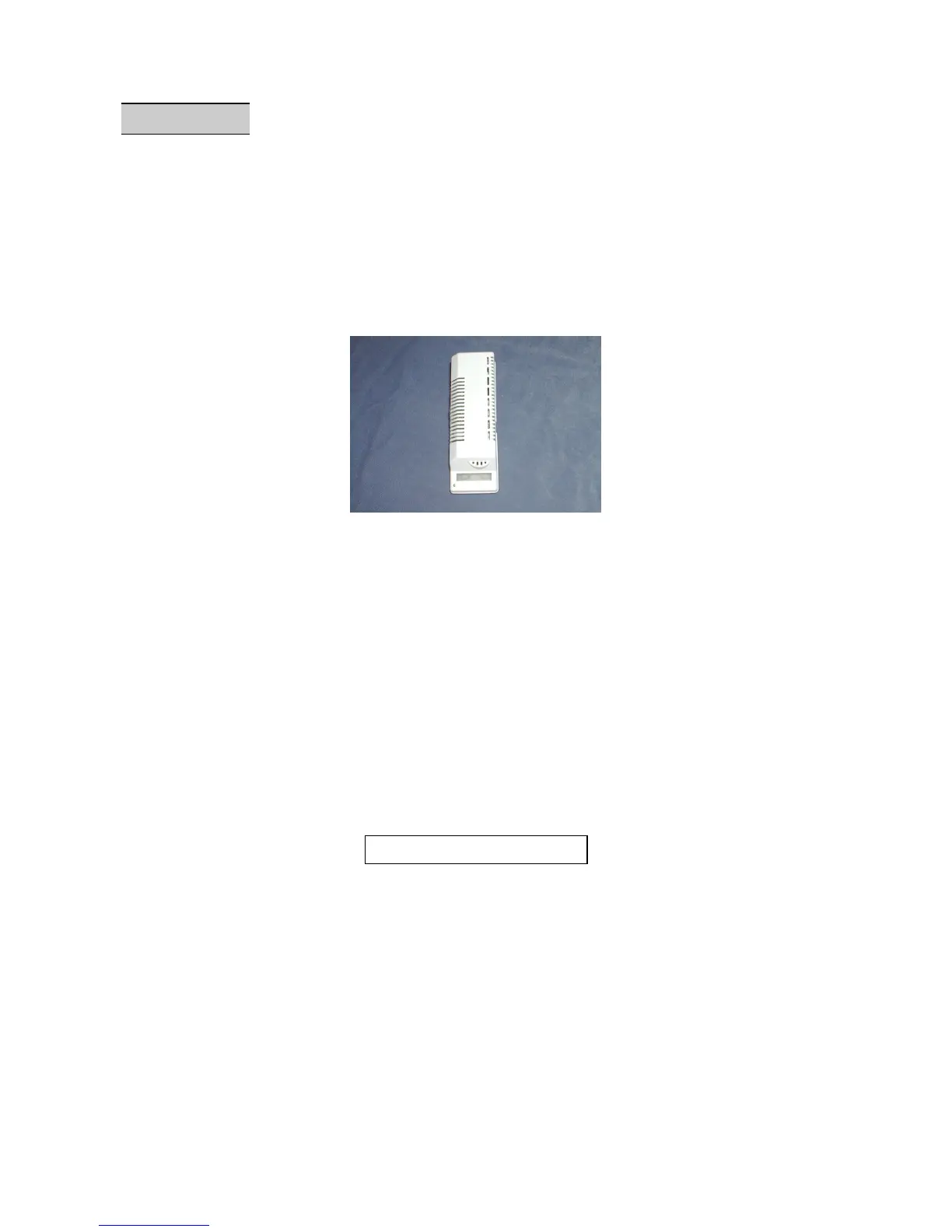
2.3.6. CO2 detector of type “Ventostat VT”
- Connection on MX48 unit: see Fig. 20.
- Resistance of detector/unit power cable: 12 ohms maximum per wire, i.e. 24 ohms in
loop.
- 4-20 mA output: maximum load = 280 ohms (whole loop)
2.3.7. Specific case of intrinsic safety detectors
Two types of intrinsic safety barrier can be used: Z787 / EX and MTL787S+.
PRECAUTIONS
Before connecting the barrier to the unit, check that the voltage is < 25 V DC.
- A short circuit in the electrical connections will result in destruction of the barrier.
- Perform wiring in the DE-ENERGIZED state.
- The electrical link between the MX48 unit and the clipper is made using a screened
cable with two active conductors with a maximum resistance of 12 ohms each.