16
2.4. Connecting the unit to external devices
2.4.1. Slaving controls
The 8 measuring channels of the MX48 unit are each equipped with two relays which can be used
to control external devices: sirens, solenoid valves, extractors, telephone calls, etc..
For each measuring channel, the relays are distributed in the following manner (see Fig. 7):
- a relay associated with the triggering of alarm 1 (fig 7),
- a relay associated with the triggering of alarm 2 (fig 7),
- use of open or closed contacts selected with a jumper (see Fig. 7 – item A),
- use of positive or negative safety selected by programming (see the CHANNEL
programming menu),
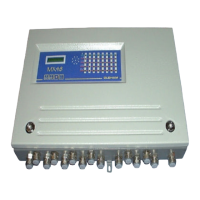
- contact outputs on the back of the measuring board (see Fig. 12).
- An example of connection is given in Fig. 24:
- a siren connected to relay AL1 will be actuated as soon as alarm 1 is triggered,
- a solenoid valve connected to relay AL2 will be actuated as soon as alarm 2 is
triggered.
For all channels:
- A common relay associated with the triggering of alarm 3 for the 8channels (fig 3).
By programming, this common relay can also be used for the remote transmission of the
audio warning signal. (This relay will then be associated with all the unit’s alarms).
- A fault relay associated with the triggering of channel faults (detector failures, electrical
connections, excessively negative zero, etc.). This relay will always be in positive safety
mode (see Fig. 3).
- The use of open or closed contacts is selected by programming on common board (see
Fig. 3).
- Common relay contact outputs on the back of the power module: Fig. 8.
REMARK
Owing to the breaking capacity of the MX48 unit’s relays which is limited to 2 A / 250 V AC or 30
V DC, external intermediate relays must be used if the devices to be controlled require high power
levels.
The relay contacts are indicated : unit switched off