8
M
M
A
A
I
I
N
N
C
C
H
H
A
A
R
R
A
A
C
C
T
T
E
E
R
R
I
I
S
S
T
T
I
I
C
C
S
S
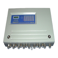
• Wall-mounted box (500 x 340 x 89)
• AC or DC power supply
• 4 or 8 measuring inputs for detectors
• Display of measurement on a plasma display panel (2 lines - 16 characters)
• One keypad with four keys on the front panel for the user
• One keypad with four keys for maintenance (on the display unit card, accessible only by
opening the front panel)
• One “CALIBRATION” key and one “PROGRAMMING” key for maintenance (on the
display unit card, accessible only by opening the front panel)
• 3 gas alarms per channel
- Two instantaneous rising or falling thresholds, manual or automatic clearing, with
“extractor control logic (tunnel parking application)”
- One rising or falling threshold, automatic clearing, triggering by time delay or
average
Relaying
Total of 10 or 18 relays distributed as follows:
- Two relays per channel, with positive or negative safety, contacts open or closed
at rest for the first two thresholds
- One relay common to channels for third thresholds or for all alarms (buzzer
transmission), with positive or negative safety, contacts opened or closed at rest
- One relay common to channels for faults and failures, constant positive safety
mode, contacts open or closed at rest.
• Current output (4-20 mA) per measuring channel.
• Common audio alarm that can be acknowledged in the case of occurrence of gas alarms.