DOLCECLIMA COMPACT
ENGLISH
EN - 19
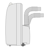
2.3 - MOBILE INSTALLATION
The air conditioner must be installed in a suitable environment.
It is recommended to reduce solar radiation through curtains, Venetian blinds and to keep doors and windows
closed.
a. Position the air conditioner in front of a window or French window.
b. Positionthemachinesideterminal(2)ontheexiblehose(1)asshownbyFig.8.
c. Positiontheterminal(3)ontheoppositesideoftheexiblehose(1)(Fig.8).
d. Insertthemachinesideterminal(2)ontheairoutletgridoftheappliance(26)asshowningure9.
e. Position the terminal (3) in such a way as to make air exit to the exterior (Fig.10)
f. Ifyoupossessaslidingwindow(verticalorhorizontal)orashutter,itispossibletousethesupplied
“SLIDERKIT”(4)whichallowsamoreecientinstallation.
FortheinstallationwithKITSLIDER,proceedasshowningures11and12.
g. Apply the adhesive seal (8) (Fig.12)
h. Position the “SLIDER KIT” (4) and adapt it (Fig.12)
i. Positiontheexiblehose(1)andapplytheseal(9)(Fig.12)
Extend the pipe only to the necessary extent, so that the air conveyor remains closed between
the xture shutters.
2.4 - FIXED INSTALLATION
Theairconditionercanalsobeinstalledwithxedholesinwindowsorwalls.
Airowmustnotbeobstructedbyprotectivemeshorsimilar.
Anyformsofprotectionmusthaveatotalcross-sectionforairowofnotlessthan140cm
2
.
a. Positionthemachinesideterminal(2)ontheexiblehose(1)asshownbyFig.8.
b. Drilla127mmholeintheglassorinthewallataheightabovetheoorincludedbetween300and1200
mm (Fig.13).
c. Position the terminal (6) in the wall hole and mark the drilling points.
d. Remove the terminal (6) and drill 6 mm holes.
e. Insert the supplied wallplugs (10) in the holes.
f. Position the terminal(6)intheholeofthewallandxitwiththesuppliedscrews(10).
g. Insertthemachinesideterminal(2)ontheairoutletgridoftheappliance(26)asshowningure9.
h. Connecttheotherextremityoftheexiblehose(1)ontheterminal(6)(Fig.14).
i. Inserttheange(7)intheterminal(6)andclosethecap(7a)whentheapplianceisnotrunning(Fig.14).
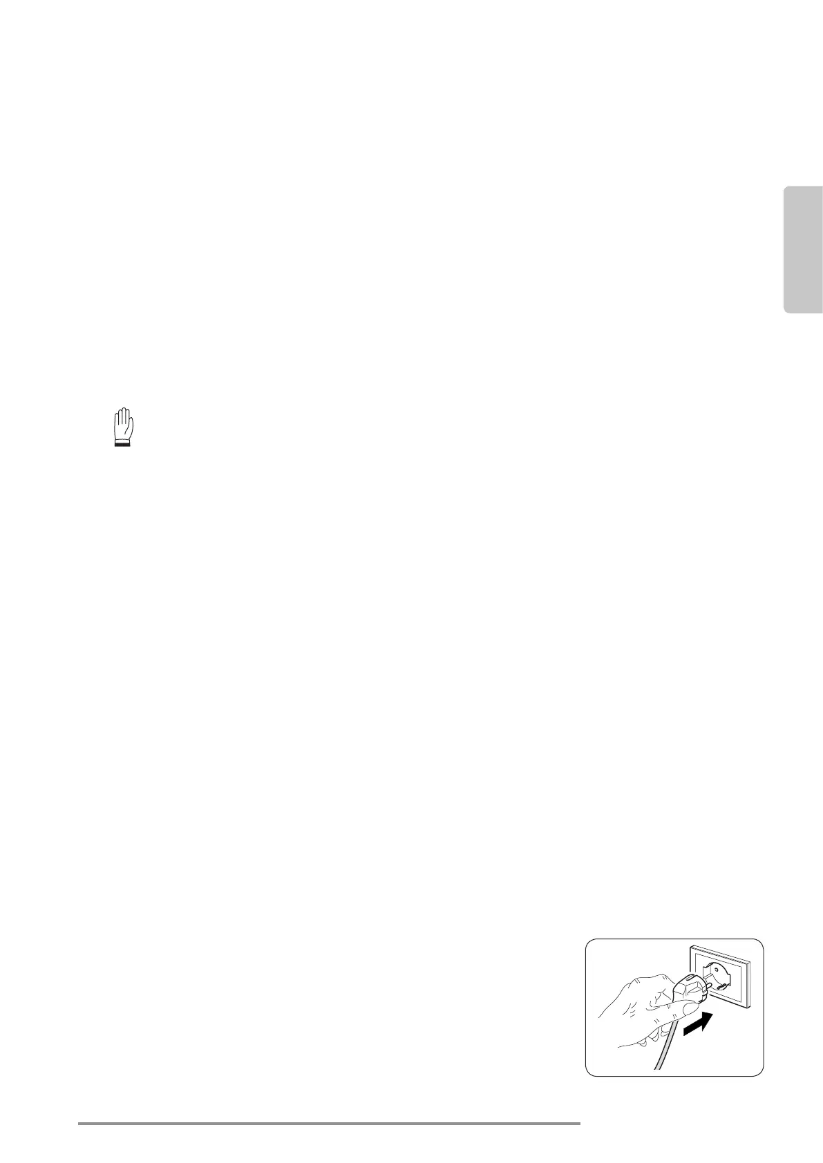
2.5 - ELECTRICAL CONNECTION
Theapplianceisttedwithapowercablewithplug.
Before connecting the air conditioner ensure that:
• Thevoltageandpowerfrequencyvaluesmatchthosespeciedonthe
appliance plate data.
• Thepowerlineisequippedwithaneectiveearthconnectionandis
correctlysizedformaximumpowerconsumptionoftheairconditioner.