Do you have a question about the Olivetti d-Color MF2613En and is the answer not in the manual?
General title for the digital copier series.
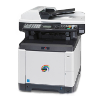
Specific models covered by the service manual.
Explanation of safety symbols used throughout the manual.
General warnings related to machine installation and operation.
Cautions to be observed during machine installation.
Detailed technical specifications for the machine models.
Identification and labeling of machine components.
Diagram illustrating the internal mechanical layout.
Requirements for the machine's installation location and environment.
Procedure for safely unpacking the machine and its components.
Instructions for installing optional expansion memory.
Procedure for accessing and executing maintenance functions.
Information on accessing and using the service mode.
Procedures for detecting and resolving paper misfeeds.
Explanation of the machine's self-diagnostic capabilities and error codes.
Guidance for diagnosing and fixing image quality issues.
Troubleshooting steps for electrical issues.
Troubleshooting steps for mechanical malfunctions.
Error codes related to scanning and sending functions.
General classification and descriptions of error codes.
Important safety precautions before disassembling the machine.
Procedures for removing and reinstalling external covers.
Disassembly and reassembly of paper feeding components.
Procedures for handling the developing unit.
Instructions for removing and reinstalling drum units.
Procedures for the transfer and separation units.
Steps for detaching and refitting the fuser unit.
Procedures for replacing various Printed Wiring Boards (PWBs).
Disassembly and reassembly of drive system components.
Procedures for detaching and refitting optical components.
Steps for removing and reinstalling the document processor.
Procedures for detaching and refitting other machine parts.
Instructions for upgrading the machine's firmware.
Important notes for replacing the engine PWB.
Description of the paper feeding and conveying mechanisms.
Details of the drum unit, charger roller, and cleaning unit.
Components and function of the developing unit.
Components of the image and laser scanner sections.
Description of the intermediate and secondary transfer units.
Details of the fuser unit, including heat roller and press roller.
Components of the paper eject and feedshift paths.
Mechanism for paper conveying during duplex printing.
Components of the original feed, conveying, and switchback sections.
Overview of the machine's main PWBs and their functions.
Identification and function of switches and sensors.
List and functions of the motors used in the machine.
Description of other electrical components like clutches and lamps.
Electrical components specific to the document processor.
Operation and connector details of the power source PWB.
Operation and connector details of the engine PWB.
Operation and connector details of the main PWB.
Operation and connector details of the drum relay PWB.
Operation and connector details of the DP drive PWB.
Supplementary information and reference materials.
Reference for identifying repetitive defects based on intervals.
Using FRPO commands for firmware reprogramming.
Information on using maintenance commands for adjustments.
Schematic diagrams illustrating electrical connections.