Y112890-3 Service Manual
1-5
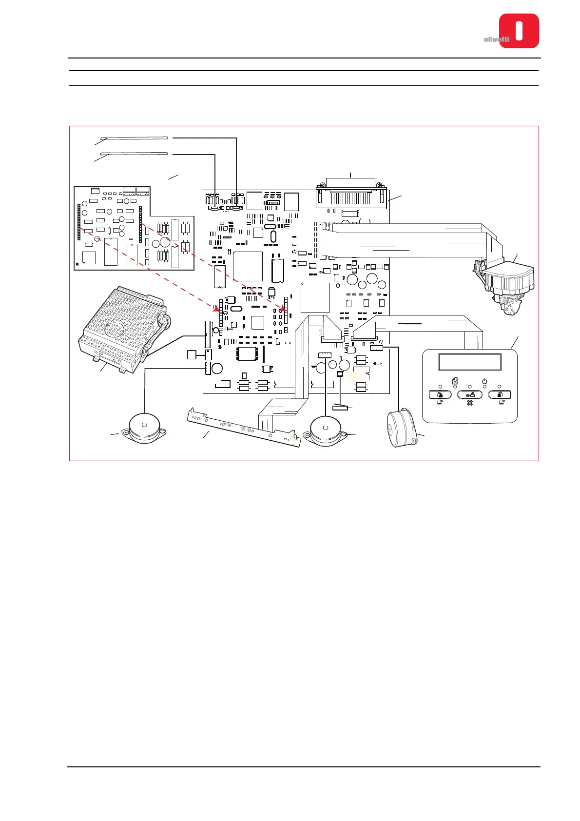
GENERAL BLOCK DIAGRAM
In the following schema are indicated also the connectors for connecting the peripherals and the motherboard.
Figure 1 - 4 Block Diagram
1 Front CIS 8 Paper feeder motor
2 Back CIS 9 Cover sensor
3
Magnetic options interface
(Horizontal Magnetic or MICR)
10 Paper presence/alignment photosensors
4 Motherboard (Version with scanner) 11 Services motor
5 Printhead 12 Power supply unit
6 Console 13 Front paper present photosensor
7 Printhead carriage motor
1
2
+
+
1
+
+
1
+
+
1
RV1
DS39
6IF
2IF
1IF
7IF
TPCS2
J3
3IF
TPCS8
TPCS9
Mech2
CS7
CS6
5IF
J2
J28
J1
J23
J20
J3
J24
J19
J26
J22
J4
JS1 JS2
J9 J10
J6
J14
J18
J13
J17
J16
MB - 2