Do you have a question about the Olivetti d-Color MF2001 and is the answer not in the manual?
Defines warning symbols used for safety and property protection.
Explains various warning, prohibition, and action symbols.
Details warnings and cautions for correct machine installation and environment.
Lists essential warnings and cautions for service personnel during maintenance.
Provides detailed technical specifications for the machine's various functions.
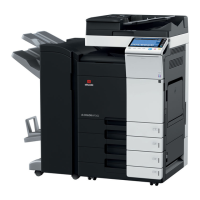
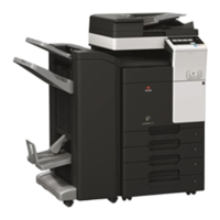
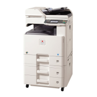
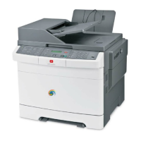
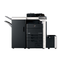
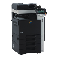
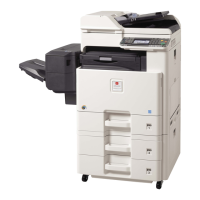
Illustrates and names the key parts of the machine's front, rear, and operation panel.
Shows a cross-sectional view of the machine's internal components and paper path.
Specifies the recommended environmental conditions for optimal machine operation.
Outlines the step-by-step procedure for unpacking and performing the initial setup.
Explains how to access and execute various maintenance functions.
Details how to enter and utilize the service mode for advanced machine settings.
Explains paper misfeed indications and locations, and how to remove jammed paper.
Describes the machine's self-diagnostic system and error reporting.
Lists error codes, their causes, and corrective actions for troubleshooting.
Presents visual examples of common image quality issues and their potential causes.
Outlines common electrical issues, their causes, and troubleshooting steps.
Details mechanical issues, their causes, and corrective measures.
Lists and explains error codes related to scanning operations (SMB, FTP, Email).
Provides critical safety and handling precautions before disassembling the machine.
Details the procedure for removing and reinstalling the front and rear outer covers.
Explains the procedure for detaching and refitting the primary paper feed unit.
Covers the procedure for detaching and refitting the developing unit.
Details the procedure for detaching and refitting the drum unit and its associated components.
Explains the procedure for detaching and refitting the intermediate and secondary transfer units.
Details the procedure for detaching and refitting the fuser unit.
Covers the procedure for detaching and refitting the conveying motor and drive unit.
Explains the procedure for detaching and refitting the laser scanner unit.
Details the procedure for detaching and refitting the image scanner unit.
Covers the procedure for detaching and refitting the LED unit.
Details the procedure for detaching and refitting the document processor.
Explains the procedure for detaching and refitting the DP paper feed roller and separation pulley.
Covers the procedure for detaching and refitting the DP main PWB.
Details the procedure for detaching and refitting various PWBs.
Provides instructions for upgrading the machine's firmware via USB memory.
Describes the mechanical construction of the paper feed and conveying systems.
Details the mechanical construction of the drum section and its components.
Explains the mechanical construction of the developing unit.
Describes the mechanical construction of the image scanner section.
Details the mechanical construction of the laser scanner section.
Covers the mechanical construction of the intermediate and secondary transfer units.
Describes the mechanical construction of the fuser section.
Explains the mechanical construction of the paper eject and feedshift paths.
Details the mechanical construction of the duplex paper conveying path.
Covers the mechanical construction of the original feed section of the document processor.
Illustrates the layout of PWBs within the machine.
Lists and describes the functions of the machine's various PWBs.
Lists and describes the functions of the machine's motors.
Describes other electrical components like clutches, sensors, and lamps.
Details the connectors and signals for the Main PWB.
Details the connectors and signals for the Engine PWB.
Details the connectors and signals for the Power source PWB.
Details the connectors and signals for the IH PWB.
Details the connectors and signals for the Operation panel PWB main.
Details the connectors and signals for the DP Main PWB.
Contains supplementary information including maintenance kits and firmware commands.
Provides a guide to page counts for detecting repetitive defects on rollers.
Explains how to use FRPO commands for reprogramming printer firmware.
Lists image adjustment procedures, maintenance modes, originals, and pages.
Provides a detailed wiring diagram illustrating component interconnections.
| Function | Print, Copy, Scan, Fax |
|---|---|
| Print Resolution | 600 x 600 dpi |
| Copy Resolution | 600 x 600 dpi |
| Scan Resolution | 600 x 600 dpi |
| Fax Resolution | 200 x 200 dpi |
| Fax Transmission Speed | 33.6 Kbps |
| Paper Capacity | 250 sheets |
| Max Paper Size | A4 |
| Duplex Printing | Yes |
| Operating System Compatibility | Windows, Mac, Linux |
| Display | LCD Touchscreen |
| Monthly Duty Cycle | 30, 000 pages |
| Type | Multifunction |
| Print Speed | 20 ppm |
| Paper Size | A4, A5, B5, Letter, Legal |
| Connectivity | USB, Ethernet |
| Interface | USB 2.0, Ethernet 10/100Base-TX |