17
P/N 30149, Rev. G [12/15/2016]
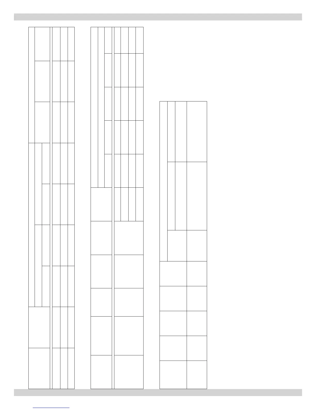
Table A-6 Direct Drive Blower Set-Up PSC Motor
Furnace Model Blower
Blower Set-Up Cooling Capacity
0.20 in. w.c. 0.50 in. w.c.
Tons Power CFM Range
Speed Motor Speed Motor
BML-60 100-10T DD Low 1/2 HP Med-Low 1/2 HP 3.5 1/2 HP 700-1400
BML-80 100-10T DD Med-Low 1/2 HP Med-Low 1/2 HP 3.5 1/2 HP 700-1400
BML-90 100-10T DD Med-Low 1/2 HP Med-High 1/2 HP 3.5 1/2 HP 700-1400
Table A-7 Direct Drive Blower Characteristics PSC Motor
Furnace
Model
Blower Motor HP Motor FLA ∆T Speed
CFM
External Static Pressure – Inches w.c.
0.20 0.30 0.40 0.50 0.60
BML
60 – 90
100-10T DD 1/2 HP 7.1 70°F
High 1722 1645 1561 1462 1375
Med-High 1604 1545 1473 1383 1302
Med-Low 1147 1133 1106 1063 1013
Low 747 738 720 702 669
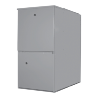
Table A-8 Direct Drive Blower Characteristics ECM Motor
Furnace
Model
Blower Motor HP Motor FLA ∆T
CFM RANGE
Continuous
Fan
Heating Cooling
0.38 - 0.48 inches w.c. 0.5 inches w.c.
BMLV
100-10T
DD
1/2 HP ECM 7.7 70°F 470-635 625 - 1500 600 - 1200
60 – 90
APPENDIX A - CHECK OUT AND ADJUSTMENTS
TIP
Formulas will assist with design of duct-work and determination of air ow delivery.
CFM = Bonnet Output / (1.085 x System Temperature Rise (∆T)
System Temperature Rise (∆T) = Bonnet Output / (1.085 x CFM)