OlympusBH‐2(BHT/BHTU)Electronics Revision2 Page11of24
LightPresetBoard
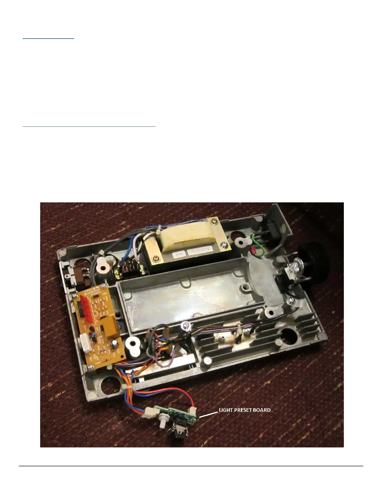
Thelightpresetboard,whichispresentonlaterstandsonly,containsasingle‐turn,500Ωlineartaperpotentiometerand
anSPDTrockerswitch(seeFigure10).WhentherockerswitchisintheOFFposition,theintensityslide potentiometer
controlsthelightingintensity,andwhentheswitchisin
theONposition,thescrewdriver‐adjustpotentiometercontrols
thelightingintensity.TheschematicforthelightpresetboardisincludedinAppendix3ofthisdocument.Asuitable
replacementforthepotentiometercouldlikelybefound,ifnecessary.However,therockerswitchismoreproblematic,
sinceitisthisswitch which
supportsthelightpreset board in the chassis.Sincethis boardis notnecessaryfor basic
operationoftheilluminationsystem,itmayberemovedandelectricallybypassedifsuitablereplacementpartscannot
be found, or to permit theinstallation of a newer electricalbaseintoan earlier stand that
does not have the chassis
notchestoaccommodatethisboard.
RemovingandBypassingtheLightPresetBoard
RemovethelightpresetboardfromtheelectricalbasebyunpluggingthetwoconnectorsfromJ1andJ2onthecircuit
board.Next,cutthetwoconnectors offofthewires,makingthecutsasclosetotheconnectorshellsaspractical,in
order to leave sufficient wire lengths for the
remaining steps.Strip the ends of the two orange wires that were
connected tothefourpinconnector and solderthemtogether,insulatingwith heat‐shrinktubinginorder to prevent
shortingtothechassis.Dothesamethingforthetwobluewires(onewasconnectedtothetwo‐
pinconnectorandthe
otherwas connected to thefour‐pin connector)andthe two red wires(one wasconnectedtothetwo‐pinconnector
andtheotherwasconnectedtothefour‐pinconnector).Besuretoroutethesesplicedwiressuchthattheywillnotbe
pinchedandwill
notinterferewiththeopticalpathoftheilluminationsystemoncethestandisreassembled.
Figure10–OlympusDV2288‐01LightPresetBoardonLaterBHT/BHTUElectricalBase (100/115VVersion)