Do you have a question about the Olympus BH-2 BHT and is the answer not in the manual?
Describes the filtered DC power supply for the comparator and LED circuits.
Explains comparator thresholds and control signal clamping for LED illumination.
Details the operation of the quad operational amplifier as voltage comparators.
Details discrepancies in LED wiring from the original Olympus manual.
Details discrepancies in the control-signal clamping network wiring.
Discusses issues with lamp house contacts and potential repairs.
Addresses erratic lamp intensity due to dust or oxidation in the control.
Notes on power transformer failure and replacement challenges.
Procedure for removing and electrically bypassing the light preset board.
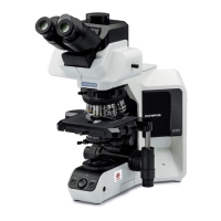
The Olympus BH-2 (BHT/BHTU) is a microscope designed for research, with a focus on providing detailed electrical circuitry information for maintenance and repair. This document serves as a comprehensive guide, supplementing the original Olympus Research Microscope Series BH2 (BHS) Repair Manual by offering additional circuit details, a complete theory of operation, and corrections to previously published circuit diagrams. The information presented is derived from tear-down inspections of functional BHTU microscopes configured for 100/115V operation.
The electrical circuitry of the Olympus BHT/BHTU microscopes is entirely contained within the base of the microscope stand. AC power is supplied via an inlet jack at the back, where the line cord connects. A power switch on the front controls illumination, and an intensity control on the right-hand side adjusts the lamp voltage. A voltage selector switch on the bottom of the base allows operation under normal or low-line conditions. Inside the base, a power transformer, a bridge rectifier, a main printed circuit board, and a power transistor work together to manage the electrical functions. A 6V/20W halogen lamp is housed in the lamp house at the rear of the stand. Later models include a light preset switch and a screwdriver-adjustable light preset control, located above the intensity slider, for photographic applications.
The BHT/BHTU electronics perform two primary functions, both controlled by a variable signal from the intensity potentiometer. The first is intensity control of the halogen lamp, achieved by dimmer circuitry that varies the voltage supplied to the lamp. The second function is the display of lamp voltage via a four-segment LED bar-graph display, which also responds to the intensity control signal.
The lamp dimmer circuitry, as simplified in Figure 1, illustrates the basic operation. Electrical power from the AC line cord is converted by transformer T101 to approximately 9V RMS. This output is then fed into bridge rectifier DB101, which provides full-wave-rectified DC to the dimmer circuitry. Transistors Q101 and Q201, being bipolar junction devices, require DC to conduct current in a single direction. The potentiometer RV101 controls lamp intensity. When RV101 is set to minimum intensity, the full output voltage of DB101 is fed to the base of Q201 via R202. In this state, Q201 does not conduct, as its base-emitter junction is not forward biased, resulting in no collector current in Q201 and no base current in Q101. Consequently, Q101 is cut off, and no current flows through the lamp. As RV101 is moved towards increasing intensity, the control signal to Q201 decreases, progressively forward biasing its base-emitter junction and increasing collector current. This collector current acts as the base current for Q101, causing it to conduct more current through the halogen lamp. The lower the control signal amplitude, the higher the lamp current and intensity. The overall DC current gain is substantial, approximately the product of the individual beta values of Q201 and Q101. This high gain ensures the halogen lamp is fully illuminated with minimal base current in Q201, resulting in a minimal voltage drop across R202. The lamp voltage can be adjusted from zero to nearly the full output voltage of DB101.
Figure 2 introduces current-limiting functionality with the addition of transistor Q202, resistor R201, and capacitor C202. Resistor R201, the current-sensing resistor, is in series with the halogen lamp. Under normal lamp current, the voltage drop across R201 is insufficient to activate Q202. However, if the lamp current becomes high enough to turn on Q202, its collector current shunts the base-emitter junction of Q201, reducing base current and, in turn, lamp current. This negative-feedback mechanism limits the peak lamp current to about 7.3A, preventing damage from power surges and minimizing thermal stresses at power-up. Capacitor C202 provides low-pass filtering for Q202's base, preventing high-frequency noise or RF from affecting the dimmer.
The LED bar-graph display circuitry, shown in Figure 3, illuminates four LEDs as the intensity control moves from minimum to maximum. The variable output from RV101 acts as the control signal for the LED display. This signal feeds the non-inverting inputs of four op-amps configured as comparators. The control signal is maximum at minimum intensity and zero at maximum intensity. Each comparator has specific switching thresholds, set to illuminate LEDs at pre-defined lamp voltages of 2V, 4V, 6V, and 7V, in response to the decreasing control signal.
The filtered DC power supply, generated by diode D201 and capacitor C201 acting as a peak detector from DB101's output, powers the comparators and LEDs. The AC ripple on this line varies with current draw. At minimal lamp intensity (all LEDs off), current draw is low, and voltage is approximately +10.5V with little ripple. As intensity increases (and LEDs illuminate), current drain and AC ripple increase, resulting in an average voltage of about +9.5V at maximum intensity.
Comparator thresholds are provided by a four-stage voltage divider (R208, R209, R210, R211, R212), allowing LEDs to illuminate at 2V, 4V, 6V, and 7V lamp voltages. Resistors R213 and R214, and diodes D202, D203, D204, form a control-signal clamp, preventing the non-inverting inputs of the comparators from dropping below approximately +0.7V. This prevents LEDs from illuminating briefly when RV101's wiper and comparator thresholds drop to zero at AC line crossings, which could lead to an indeterminate state and unwanted LED illumination. The clamp ensures that if the control signal is low enough to forward bias D202, the voltage on the non-inverting inputs is clamped to +0.7V. As RV101's wiper voltage increases, D202 turns off, allowing the control signal to swing positive without restraint, but preventing it from dropping below +0.7V.
Integrated circuit IC1, a NEC uPC324C quad operational amplifier, operates open-loop as voltage comparators. Each comparator drives its associated LED low when the clamped control signal drops below its threshold voltage, illuminating the LED. It drives its output high when the control signal exceeds the threshold, extinguishing the LED. The power-on indicator is LED "A" and resistor R203.
During the research for this document, two errors were identified in the Olympus Research Microscope Series BH2 (BHS) Repair Manual's schematic diagram, both in the LED bar-graph display circuitry. The first error concerns the wiring of the four bar-graph LEDs. The Olympus manual shows LEDs wired with cathodes to comparator outputs and anodes to current-limiting resistors. However, the actual circuit configuration has anodes connected to the filtered DC power supply line and cathodes to current-limiting resistors. While both configurations would work, the actual as-built configuration is detailed here. The second error is in the wiring of the control-signal clamping network. The Olympus manual depicts this network fed from the full-wave-rectified output of the bridge rectifier, but the actual circuit is fed from the filtered DC power supply line. This error is more significant, as the published circuit would not guarantee that LEDs remain off around AC line zero crossings.
To access the electronics for maintenance, the electrical base must be removed from the stand. It is crucial to take notes and photographs during disassembly for correct reassembly. Before removal, check for a light preset control and switch on the right-hand side, as earlier units lacked these. All major components (AC power cord, condenser, stage, eyepieces, viewing head, objectives) should be removed from the stand to prevent damage. The top of the arm should be covered with a plastic bag to prevent dust. The lamp house should be removed by grasping and pulling it straight back, taking care not to touch the halogen lamp with fingers. The stand is then turned upside down, and four hex cap screws are removed using a 5/32" Allen tool. The stand is lifted from the electrical base, ensuring the light preset control board (if present) is disengaged from the chassis notch. The stand is then placed on a clean, flat surface, and the electrical base is set up for troubleshooting. The lamp house is carefully plugged into J103 on the rear of the electrical base, ensuring contact pins engage mating receptacles. The lamp house will be fragile without the stand's support.
For troubleshooting, with the AC line cord unplugged and the power switch off, plug the line cord into the AC inlet jack. Exercise extreme caution as lethal line voltage will be present at exposed points. Plug the line cord into a grounded AC receptacle. Never operate the microscope if the chassis bonding screw for the ground pin of the AC inlet jack is loose, missing, or if the wire is cut or damaged, as these are critical safety components.
Common problems include bad or intermittent contacts in the lamp house and erratic lamp intensity due to dust, dirt, and oxidation in the intensity control. Worn or oxidized contacts in the lamp socket can cause the halogen bulb to flicker or not illuminate. A temporary repair involves disassembling and cleaning oxidized contacts with emery paper, but replacing the lamp socket is recommended. Erratic lamp intensity from the control slider can often be corrected by spraying volume control/contact cleaner into the intensity control (with power removed) and moving the slider through its range of motion. Allow the cleaner to evaporate before reapplying power.
Olympus no longer supports BHT/BHTU microscopes, so factory replacement parts are scarce. Some electrical parts and suitable substitutes are available from third-party sources. Replacement electrical components can also be salvaged from spare electrical bases. If exact replacements are unavailable, ensure substitutes have suitable electrical and mechanical specifications and are installed safely. The power transformer rarely fails, but a suitable substitute may be difficult to find due to its unique form factor.
The bridge rectifier is an S15VB10 (100V 15A) chassis-mount bridge rectifier with push-on terminals. A substitute should have a continuous current rating of 15A or more and a PIV rating of at least 100V. Replacements like NTE5322, KBPC1501, or KBPC1502 should be installed with thermal paste between the part and chassis for heat flow.
The lamp intensity control is a 500Ω sliding potentiometer with linear taper, manufactured by Noble, with 60mm of travel and 65mm mounting hole spacing. Cleaning with contact cleaner is recommended before replacement. A substitute should have a power rating of at least 1/2W.
Later models include a light preset board with a single-turn, 500Ω linear taper potentiometer and an SPDT rocker switch. When the rocker switch is OFF, the intensity slide potentiometer controls lighting. When ON, the screwdriver-adjust potentiometer controls lighting. If a replacement potentiometer is needed, one can likely be found. The rocker switch is more problematic as it supports the board in the chassis. If suitable replacements are unavailable, the board can be removed and bypassed to allow installation of a newer electrical base into an older stand. To bypass, unplug connectors from J1 and J2, cut connectors off wires, strip ends of orange wires and solder them together (insulating with heat-shrink tubing), and repeat for blue and red wires. Route spliced wires to prevent pinching or interference with the optical path.
The AC power switch is an Alps SDT-7 chassis-mount DPST rocker switch with a TV-5 rating for UL/CSA. It cannot be cleaned due to lack of openings. Mounting holes are 34mm on center.
The voltage selector switch is a chassis-mount DPDT slide switch rated for 4A/125VAC and 2A/250VAC. The slide protrudes 3/8" from the mounting surface, and mounting holes are 1-1/8" on center. It can be cleaned with contact cleaner through openings at both ends. The low-voltage position is rarely needed, and if a compatible replacement is unavailable, the switch can be bypassed to hardwire the microscope to its nominal operating voltage. A SPDT replacement could be used as only one pole is used.
The UYPC48 main printed circuit board rarely needs replacement as its circuitry is simple and usually repairable. Most components can be readily found. The 5-LED module is the hardest to find but can be replaced with five separate rectangular LEDs. The uPC324C op-amp can be replaced with the LM324C (DIP package). Transistors Q201 and Q202 can be replaced with 2N3906 PNP devices (accounting for pinout differences). Diode D201 can be replaced with a 1N4002 or 1N4004 rectifier diode, and D202, D203, D204 with 1N916 or 1N4148 small-signal diodes. The 0.1Ω 5W power resistor, R201, runs very hot, and its solder joints can fail. Resoldering R201's leads may fix an inoperative lamp dimmer. R201 can be replaced with a Vishay CP0005R1000JE14 part. In rare cases of irreparable damage, an aftermarket replacement board (J.C. Ritchey Company, LLC) is available, including a replacement power transistor and mounting insulator.
The power transistor Q101 is a Toshiba 2SD867 NPN power transistor in a TO-3 metal package. This obsolete part can still be found but may be expensive. The STMicroelectronics BUX10, also obsolete, is a suitable replacement. The NTE36 (TO-3P insulated case) is a good substitute available from Allied Electronics and Amazon. Any replacement transistor must be installed with suitable mounting hardware to electrically isolate the collector tab from the chassis and thermal paste to enhance heat conduction. Look for an NPN part with a collector current rating of at least 15A, a collector-to-emitter voltage rating of at least 100V, and a current gain of at least 40, in a suitable power package.
For safety, always replace the AC inlet jack with an equivalent part. Ensure the chassis-bonding screw for the ground terminal is present and secure, and the grounding wire is undamaged. If a suitable replacement jack cannot be found, a filler plate can be fabricated with a hole for an AC line cord and strain-relief grommet. The ground conductor of the power cord must be securely bonded to the chassis.
Two styles of lamp house were used: the original LS20-H (Olympus part number 5-LB402) without a metal reflector, and the later LS20H-M2 (part number 5-S119) with a reflector for more usable light. The LS20H-M2 is directly interchangeable and should be used whenever possible. A repair kit for the lamp house is available from J.C. Ritchey Company, LLC, including a replacement back cover and a new G4 lamp socket. This kit requires soldering. Alternatively, defective lamp houses can be sent to J.C. Ritchey Company for in-house repair/exchange.
As an alternative to the repair kit, a Bender and Wirth 990 lamp socket can be used. To replace the socket, remove the halogen lamp (without touching the glass), then the reflector (if present) by removing its securing screw. Remove the back cover by gently heating its perimeter to loosen adhesive, pushing from inside behind the lamp socket with a screwdriver. Avoid direct heat or pressure on ventilation slots. Clean off remaining adhesive, and remove the two screws securing the old socket. Unsolder the two wires, trim and strip wires on the new socket to match the original, and solder the new socket in place. Reinstall the screws, back cover (with epoxy), and lamp reflector. Reinstall the halogen lamp (or a new one), again avoiding touching the glass. If touched, clean with isopropyl alcohol.
The BHT/BHTU stand uses a Philips #7388 halogen projector lamp with a clear quartz envelope and a G4 base. This lamp has a color temperature of 3200K, a color rendering index of 100, and outputs 475 lumens, rated for 6V/20W with an advertised life of 100 hours at full brightness. The Philips #7388 can be purchased from Bulbworks or Amazon. Other suitable lamps include Osram 54261 or 64250 HLX, Ushio FHE/ESB (1000532), GE 778 (49718) or 788 (943117), Nikon 79099, Olympus 8-C405, Reichert 11143, and Swift MA-780.
| Type | Biological Microscope |
|---|---|
| Focusing | Coaxial coarse and fine focusing knobs |
| Microscope Type | Upright |
| Observation Method | Brightfield, Phase contrast, Darkfield |
| Optical System | Infinity-corrected |
| Eyepieces | WHK 10x/20 |
| Objectives | Achromatic, Plan Achromatic |
| Nosepiece | Quadruple or Quintuple revolving nosepiece |
| Stage | Mechanical stage with coaxial controls |
| Illumination | 6V 30W halogen lamp |
| Condenser | Abbe condenser, phase contrast condenser |
| Diopter Adjustment | Yes (on at least one eyepiece) |