OlympusBH‐2(BHT/BHTU)Electronics Revision2 Page2of24
Introduction
Thisdocumentprovidesadetaileddescriptionoftheelectricalcircuitryofthe100/115VversionoftheOlympusBHTand
BHTUmicroscopes,whicharepartofthe BH‐2family.The information contain herein is intendedtosupplementthe
information publishe d in the Olympus Research Microscope Series BH2 (BHS) Repair Manual,
by providing additional
circuit details and a complete theory of operation, as well as correctingerrorsthatwerefound in thecircuit diagram
published by Olympus.This information was obtained by performing tear‐down inspections of functional BHTU
microscopesconfiguredfor100/115Voperation.
SafetyWarningsandDisclaimers
The content of this document is provided for informational purposes only, with no expressed or implied warranties
whatsoever,including,butnotlimitedto,function,suitability,safety,accuracy,andcompletenessofinformation.
Repairing your own micr oscope may seem like a hip and cool thing to do that will mak e you the envy
of all of your
friends, but being dead will not.Potentially lethal voltages are present inside these microscopes.Do not attempt
repairs or troubleshooting if you lack the necessary skills, training, and confidence to safely perform repairs on line‐
poweredelectricalequipment.Ifyouchoosetoattemptrepairsortroubleshooting,
dosoatyourownrisk.
OverviewofElectricalCircuitry
The electrical circuitry of the Olympus BHT/BHTU microscopes resides completely within the base of the microscope
stand.ACpowerisprovidedbyanACinletjackontheback,wherethelinecordconnects.Thereisapowerswitchon
the front to turn the illumination on and off, as well
as an intensity control on the right‐hand side to vary the lamp
voltage.There is a voltage selector switch on the bottom of the base to allow operation under normal or low‐line
conditions,andenclosedwithinthebaseareapowertransformer,abridgerectifier,amainprinted
circuitboard,anda
powertransistor.A6V/20Whalogenlampresidesinthelamphouseontherearofthestand.Later standshavealight
presetswitchandascrewdriver‐adjustablelightpresetcontrol,locatedjustabovetheintensityslider,toprovidepreset
lightingintensityforphotographicapplications.
The BHT/BHTU
electronics performs two independent, yet related functions, in response to a variable control signal
from the intensity potentiometer.The first function is intensity control of the halogen lamp.To provide this, the
dimmercircuitryvariesthevoltageappliedtothelampinresponsetothiscon trolsignal.Thesecondfunction
isdisplay
of the lamp voltage via a four‐segment LED bar‐graph display, which also operates off of the intensity control signal.
Detailsofbothofthesecircuitfunctionsaredescribedinthesectionsbelow.
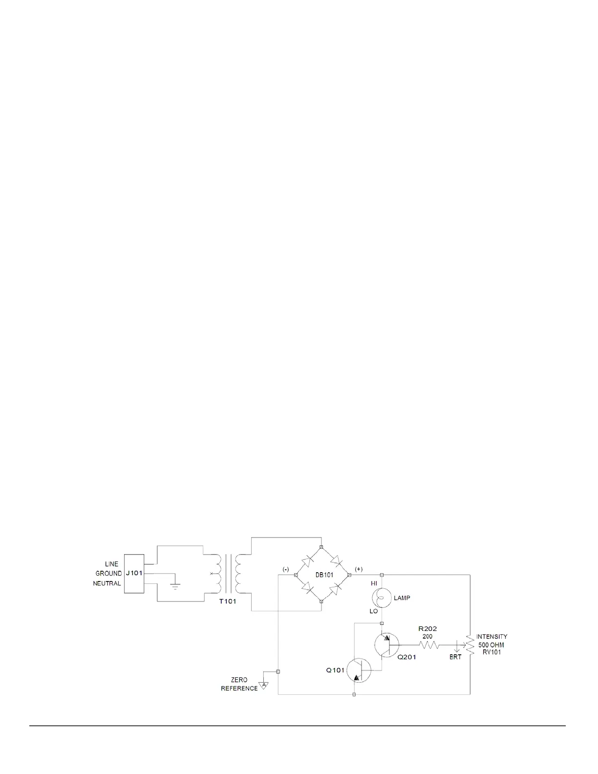
LampDimmerCircuitry
Figure1isasimplifiedschematicdiagramofthelampdimmercircuitry.Thisdiagramcontainsthedetailsnecessaryfor
an understanding of the basic operation of the lamp dimmer.Unnecessary details such as such as switching, fusing,
electricalinterconnects,andcurrentlimitinghavebeenomittedforclarity.RefertoAppendix2
andAp pendix3ofthis
documentforcompleteanddetailedschematicdiagramsoftheBHT/BHTU electronics.
Figure1–BHT/BHTULampDimmerCircuitry(withoutCurrentLimiting)

 Loading...