OlympusBH‐2(BHT/BHTU)Electronics Revision2 Page3of24
ElectricalpowerfromtheAClineisappliedtotheequipmentviatheAClinecord,whichplugsintoJ101onthebackof
the microscope base.Power transformer T101 converts the AC line voltage (120V or 240V, depending on which
transformer is installed) to approximately 9V RMS on the secondary
winding .The output of the secondary winding
feeds into bridge rectifier DB101, whose full‐wave‐rectified output in turn feeds the lamp dimmer circuitry.Bridge
rectifierDB101isnecessarytoprovideDCtothelamp dimmercircuitry,sincetransistorsQ101andQ201inthedimmer
circuitarebipolarjunctiondevices
whichcanconductcurrentinonlyasingledirection.
PotentiometerRV101controlsthelampintensity. WhenRV101isadjustedforminimumintensity(i.e.,thewiperis at
the top end of its travel), the full output voltage of bridge rectifier DB101 is fed to the base of transistor Q201 via
resistor
R202.Under this condition, transistor Q201 will not conduct since the base‐emitter junction is not forward
biasedandtherewillbenocollectorcurrentinQ201,andthere forenobasecurrentintransistorQ101.Withoutbase
current,transistorQ101willbecutoffandnocurrentwillflowthroughthe
lamp.
AspotentiometerRV101ismovedfromitsminimumintensitypositioninthedirectionofincreasingintensity(i.e.,the
wiperismovedtowards thezero referenceground), thecontrol signalfeedingthebaseoftransistor Q201decreases,
progressivelyforwardbiasingits base‐emitterjuncti on andallowing ittoincreasinglyconduct collector
current.Since
thecollectorcurrentoftransistorQ201isthebasecurrentoftransistorQ101,Q101inturnbeginstoconductincreasing
amountsofcollectorcurrent, whichflowsthroughthehalogenlamp.Thelowertheamplitudeofthecontrolsignalfrom
thepotentiometer,thehighertheresultinglampcurrentand
correspondinglampintensity.
The overall DC current gain of the lamp dimmer is considerable, and is approximately equal to the product of the
individualβvaluesoftransistorsQ201andQ101(i.e.,β
OVERALL
~β
Q201
xβ
Q101
).Becauseofthishighvalueforβ
OVERALL
,the
halogen lamp will be fully illuminated with little base current in transistor Q201, thereby introducing only a minimal
voltagedropacrossresistorR202.Neglectingthisminimaldrop,thevoltagepresentonthebottomterminalofthelamp
is approximately 0.7V higher than the control signal from the potentiometer, at
any setting of the potentiometer
(excluding the minimum‐intensity setting, where there is no forward bias on the base‐emitter junction of transistor
Q201).Thismeansthatthelampvoltagemaybeadjustedfromzeroatoneextremeoftheintensitycontroltonearly
thefulloutputvoltageofDB101
attheotherextremeoftheintensitycon trol.
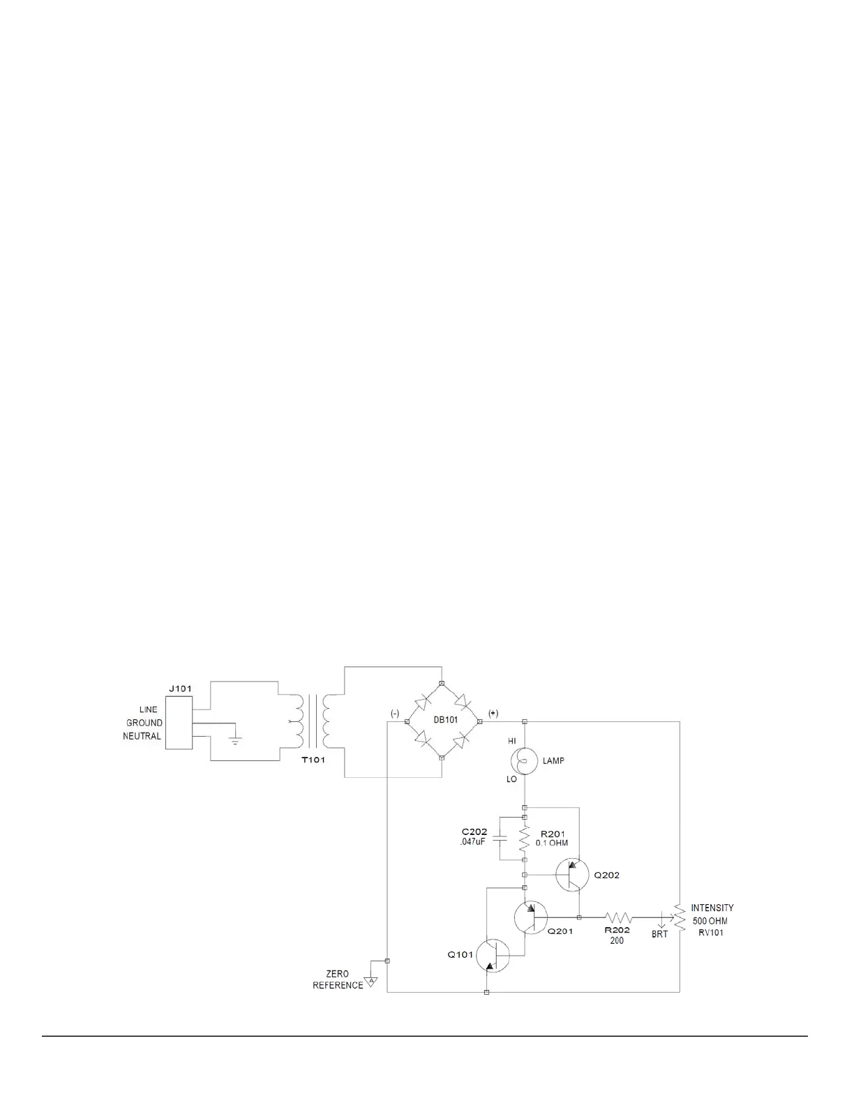
Figure2isthelampdimmercircuitryshowninFigure1withtheadditionoftransistorQ202,resistorR201,andcapacitor
C202.Thesethreecomponentsprovideacurrent‐limitingfunctionforthedimmer,topreventdamagetothelampin
theeventof
powersurgesontheAClineandtominimizethermalstressesonthelampatpower‐up.
Figure2–BHT/BHTULampDimmerCircuitry(withCurrentLimiting)
 Loading...