OlympusBH‐2(BHT/BHTU)Electronics Revision2 Page4of24
ResistorR201,thecurrent‐sensingresistor,iseffectivelyinserieswiththehalogenlamp.Solongasthelampcurrent
remainswithinthenormalrange,theresultingvoltagedropacrossresistorR201isinsufficienttoinitiateconductionof
transistorQ202,andthedimmeroperatesasdescribedintheparagraphsabove.However,
ifforanyreasonthelamp
currentgetshighenoughthatthevoltagedropacrossresistorR201issufficienttoturnontransistorQ202,theresulting
collectorcurrentoftransistorQ202shuntsthebase‐emitterjunctionoftransistorQ201,reducingitsbase currentandin
turnreducingthelampcurrent.
Thisnegative‐feedbackmechanismlimitsthepeaklampcurrenttoapproximately7.3 A.
CapacitorC202provideslow‐pass filtering for the base of transistor Q202, preventingany high frequency noiseor RF
fromaffectingthelampdimmer.
Figure 21, Figure 22, and Figure 23 show the voltage and current waveforms of
the halogen lamp with the dimmer
operating at the 100%, 50%, and 20% settings of the intensity control, respectively.Figure 24 shows the dimmer
operatingundercurrent‐limitingconditionsatthe80%settingoftheintensitycontrolandwithanabnormallylowlamp
resistanceof0.2Ω.
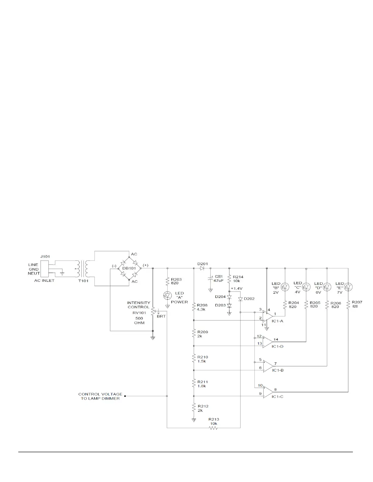
LEDBar‐GraphDisplayCircuitry
Figure 3 is a simplified schematic diagram of the LED bar‐graph display circuitry.This diagram contains the details
necessary for an understanding of the basic operation of the LED circuitry.Unnecessary details such as such as
switching,fusing,andelectricalinterconnectshavebeenomittedforclarity.RefertoAppendix2
andAppendix3ofthis
documentforcompleteanddetailedschematicdiagramsoftheBHT/BHTU electronics.
This circuit successively illuminates the four LEDs in the bar‐graph module as the intensity control is moved from its
minimum setting to its maximum setting.The variable output from the wiper of potentiometer
RV101 acts as the
control signal for the LED display circuitry (as well as for the dimmer circuit described earlier), which feeds the non‐
inverting inputs of four op‐amps used as comparators.The control signal is at maximum amplitude at the minimum
intensitysetting,andisatzeroamplitudeat
themaximumintensitysetting.Thefourcomparatorseachhavespecific
switching thresholds, which are configured to allow the comparators to illuminate the LEDs at four pre‐defined lamp
voltagesof2V,4V,6V,and7V,inresponsetothedecreasingcontrolsignalfromtheintensitypotentiometer.
Figure3–BHT/BHTU
LEDBar‐GraphDisplayCircuitry
 Loading...