27
4
Exciter Balancer U-EXBABG/EXBAUB/EXBAUG (for exclusive use with the BX-RFA/RFAA)
}When a fluorescence image obtained by multiple excitation of U/B/G is observed with dual- or triple-band fluorescence
mirror units, use the exciter balancer to select the balance between the excitation light intensities of the fluorochromes.
* To use an exciter balancer with the BX-RFAA, remove the adjustment lever and attach it to the opposite end.
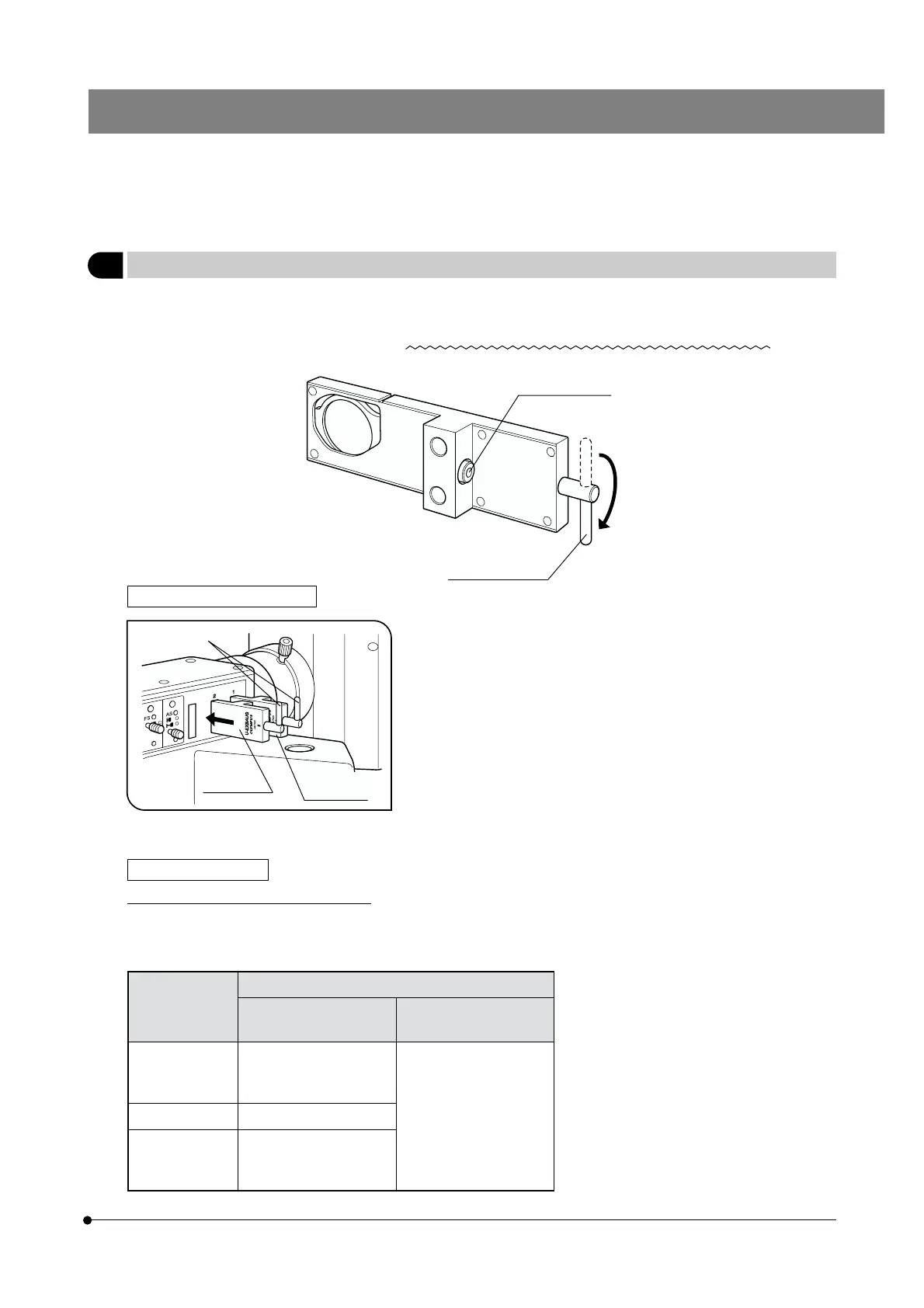
Clamping screw
Installation Procedure (Fig. 9)
1. Stand the adjustment lever @ of the exciter balancer vertically and insert
it the ND filter insertion slot with the same number as the slider on the
rear part of the right side of the illuminator.
· The insertion position is variable depending on the type of the exciter
balancer.
· Always insert the exciter balancer so that the clamping screw faces to-
ward the rear.
2. Tighten the clamping screw using the Allen screwdriver.
Operation Procedure
Observing a Double Stained Specimen
1. Set up normal reflected fluorescence observation.
2. Mount the fluorescence mirror units for double staining and engage them in the light path.
}Olympus standard products
Fluorescence Mirror Units
Exciter Balancer
Fluorescence Mirror
Units for Double Staining
Fluorescence Mirror
Units for Triple Mounting
U-EXBABG · U-DM-FI/TR2
· U-DM-FI/PI2
· U-DM-FI/TX2
· U-DM-DA/FI/TR2
· U-DM-DA/FI/PI2
· U-DM-DA/FI/TX2
U-EXBAUB · U-DM-DA/FI2
U-EXBAUG · U-DM-DA/TR2
· U-DM-DA/PI2
· U-DM-DA/TX2
# Due to its characteristics, the G-excitation
has a narrower intensity control range than
the U- and B-excitation. The intensity con-
trol range is also variable depending on
the status of specimen and variance in
mirror units’ characteristics.
# Lighting irregularities may be observed on
the upper and lower edges of the field dye
to the rotation angles of filters and the vari-
ance in mirror units’ characteristics. How-
ever, these lighting irregularities do not af-
fect the photographed area.
Fig. 9
Adjustment lever*
@
U-EXBAUG
U-EXBABG
U-EXBAUB