27
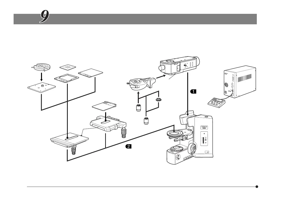
ASSEMBLY
}For assembly of the BX-UCB control box and U-HSTR2 hand switch, refer to their instruction manual.
#If the connector of the U-UCD8A motorized universal condenser is attached to the BX-UCB, the BX-RLAA motor-
ized reflected light illuminator cannot work normally. Be sure to unplug the connector if it is connected.
Rotary wafer holder
BH2-WHR43
Wafer holder
U-WHP2
* Warp prevention pins (2 for each) are attached on the bottom sides of the U-MSSP/MSSP4 stage plate and the
U-MSSPG glass plate when the system is shipped from the factory. Remove the pins before use.
Note 1) With certain motorized revolving nosepieces, the connector of the BX-RLAA illuminator should be unlocked
before operation.
Glass plate
U-MSSPG*
Stage plate
U-MSSP4*
Stage plate
U-MSSP*
4 x 4 inch stage
U-SIC4R2/SIC4L2
Stage
U-SVRM/SVLM
Stage
clamping
screws
Motorized revolving
nosepiece
Note 1)
Brightfield/
darkfield
objective
Brightfield
objective
Objective
adapter
BD-M-AD
Revolving
nosepiece
clamping screw
Motorized reflected light
brightfield/darkfield illuminator
BX-RLAA
Microscope frame
BX61TRF
Control box
BX-UCB
Hand switch
U-HSTR2