BX51
13
CAUTION
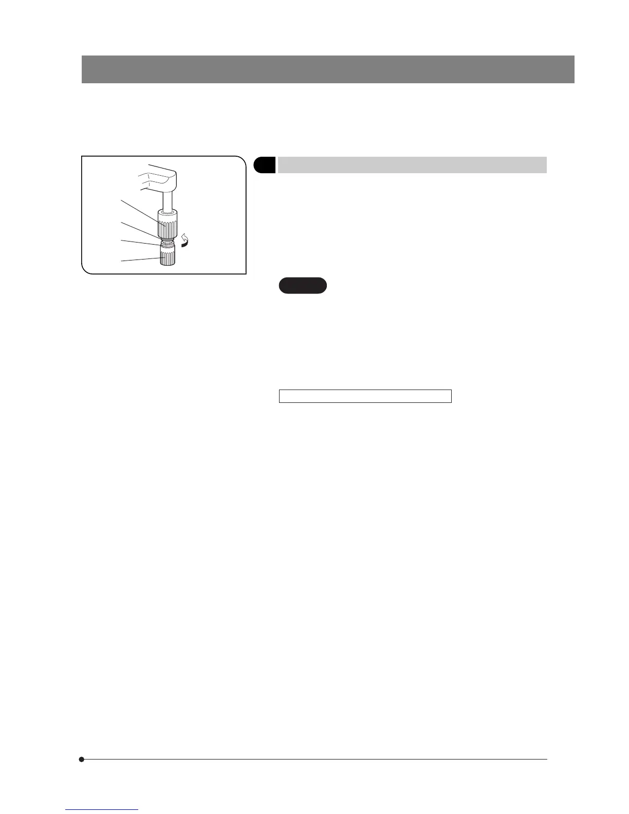
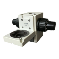
2 Adjusting the X- and Y-Axis Knob Tension
(Fig. 17)
Fig. 17
@
²
³
|
1. Hold the X-axis knob @ and slide up the Y-axis knob ² up to expose the
adjustment knobs.
2. Turning the X-axis adjustment knob ³ or Y-axis adjustment knob | clock-
wise (in the direction of the arrow) increases the tension and counter-
clockwise decreases it.
# If the tension is adjusted to tight, a creaking sound may be heard
during stage travel, and the stage stopping accuracy may be imper-
iled.
After long hours of use, the stage guide may be devi-
ated and the stage travel range may be decreased.
However, this is not malfunction and can be corrected
easily as described below.
[Treatment]
Horizontal direction: Hold the specimen holder and move the stage guide
to the left and right so that it hits the stoppers.
Vertical direction: Hold the upper stage and move it to the front and rear
so that it hits the stoppers.
Stage Feed Knob Rubber Caps (Optional)
}When the X- and Y-axis knobs are fitted with the rubber caps, the knobs
can be adjusted without slipping and fine adjustment is possible by
holding the knobs with a very light force. The knob rubber caps also
reduce fatigue after long hours of operation.
The U-SHGT thick type (thickness 5 mm) and U-SHG thin type (thickness
2 mm) knob rubbers are available.
To attach the knob rubbers:
First fit the larger knob rubber to the Y-axis (upper) knob from below it,
then fit the smaller knob rubber to the X-axis (lower) knob from below it.