DP71
10
Fig. 5
Fig. 6
Fig. 7
3
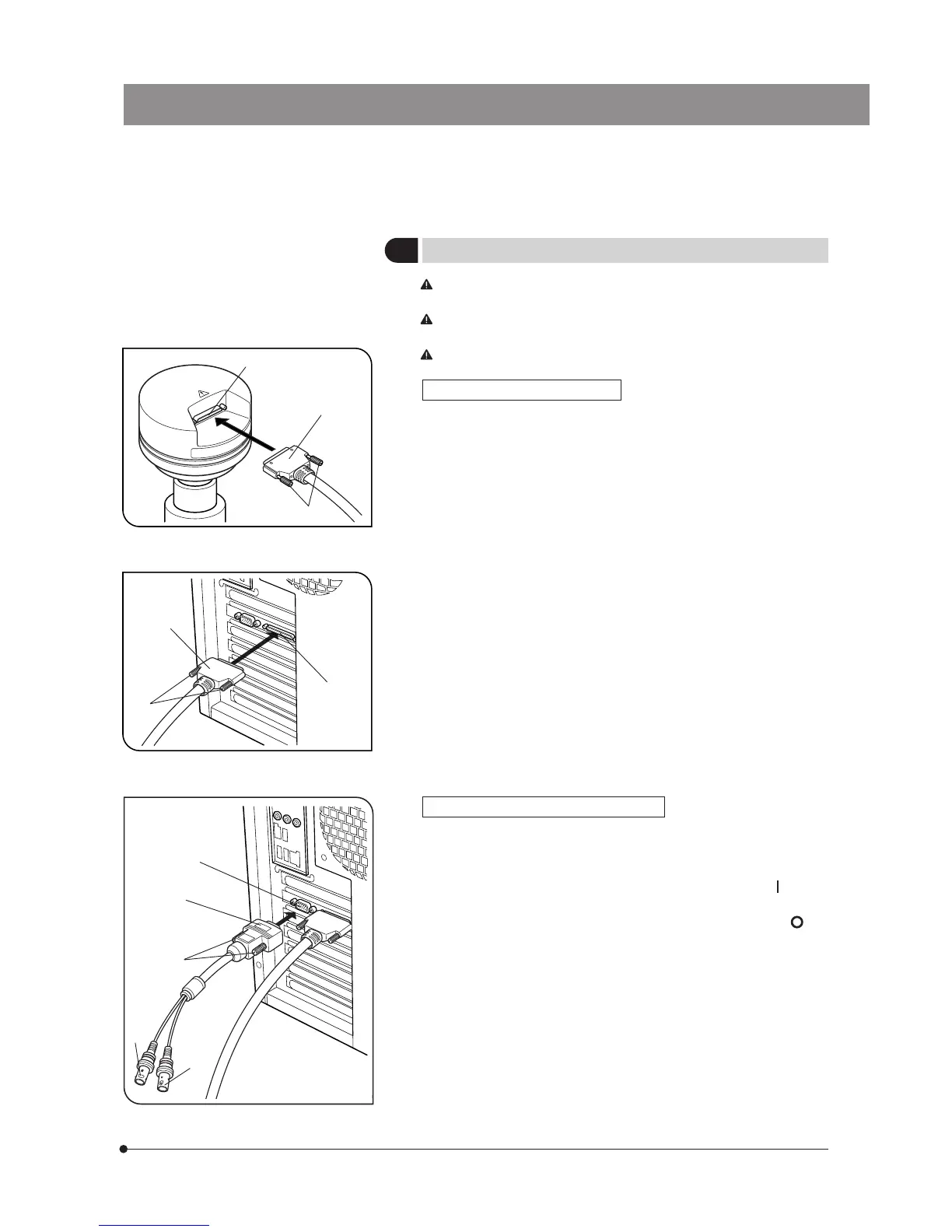
Connecting the Cables
The cords and cables are vulnerable to bend or twist. Do not apply
excessive force to them.
Be sure to switch off the computer before proceeding to the
connections.
Always use the cables designated by Olympus.
Connecting the Interface Cable
1. Connect the connector @ on one end of the interface cable to the
connector ² on the PCI interface board, tighten the lock screws ³ on
the interface cable’s connector and check that the cable will not slip out.
2. Connect the connector | on the other end of the interface cable to the
connector 5 on the camera head, tighten the lock screws 6 on the
interface cable’s connector and check that the cable will not slip out.
Connecting the External Trigger Cable
1. Connect the connector @ of the external trigger cable to the connector
² on the PCI interface board, tighten the lock screws ³ on the external
triggering cable’s connector and check that the cable will not slip out.
2. When using the trigger input, connect the red cable (marked “ ” ) to the
BNC connector |.
3. When using the trigger output, connect the blue cable (marked “ ” ) to
the BNC connector 5.
²
@
³
|
5
6
@
5
²
³
|