4-3
OEP-3 V1 (UC)
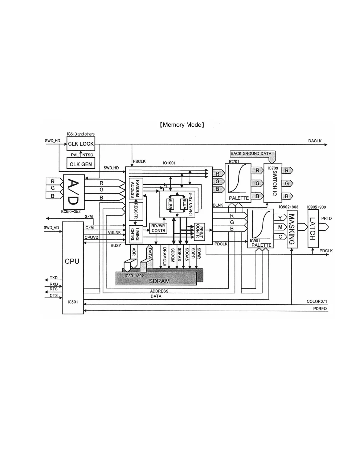
Memory mode
In this mode, the image data fetched into DRAM is output to the monitor.
The flow of an image signal is as described below.
The digital image data fetched into DRAM is read using a DRAM control circuit (CXD9111R: IC1001)
and converted from 32 bits to 8 bits. After that, the image data is adjusted in color using a color
adjustment circuit (IC701), and the image size is adjusted by the blanking produced using a DRAM
control circuit. The resultant data is converted from digital to analog and output to the analog signal
processing block.